1-4 GENERAL MDS 05-2415A01, Rev. A
alarm, transmit keyline activity and transmit status. When used with the modem option, an
annunciator panel indicates the status of the RS-232 interface lines (TXD, RXD, DCD, RTS,
CTS). If desired, the LED display can be turned off by moving a jumper inside the radio.
This may be desirable in applications where power consumption must be kept to an absolute
minimum.
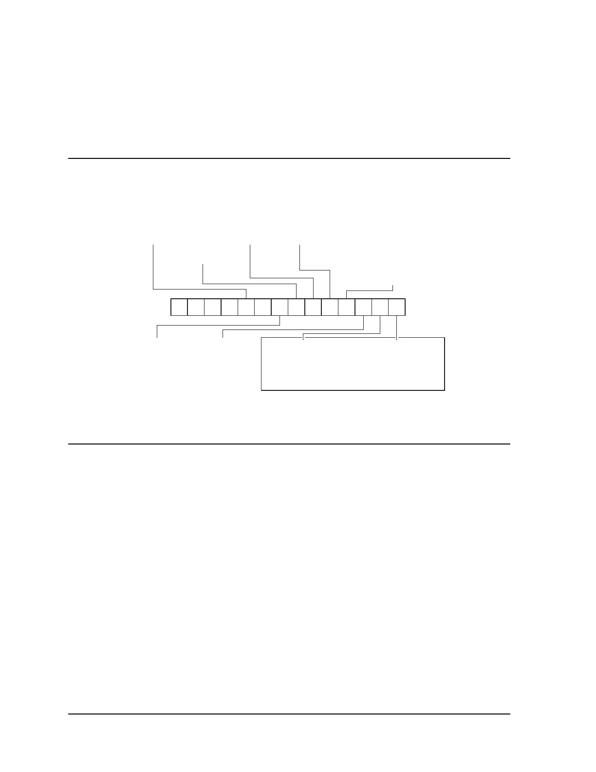
MODEL NUMBER CODES
The model number as found on the serial number label may be used to determine the general
hardware configuration of the radio as it was shipped from the factory. Figure 1-1 illustrates
the significance of the various characters in the radio’s serial number. The serial number
label is located on the end of the radio enclosure.
POWER SETTING
(1) 12VDC
INTERFACE
(0) 4-Wire Audio
(2) 1200 BPS
(A) 4800 BPS
(D) 9600 BPS
DIAGNOSTICS
(0) None
(4) Remote Maint.
SAFETY CERTIFICATION
(0) N/A
(F) Factory Mutual / UL
OPERATION
(R) Base/Remote
BANDWIDTH
(1) 12.5 KHz
SEPARATION
(5) 5–10 MHz/Simplex
REGULATORY CERTIFICATION
(0) N/A
(1) FCC (USA)
(2) DOC RSS-119
(3) DOC RSS-122 (Canada)
FREQUENCY RANGE
(A) 390–406 MHz*
(E) 450–470 MHz*
(F) 406–430 MHz*
(G) 350–370 MHz
(H) 370–390 MHz
(I) 390–410 MHz
* 2013 printed circuit board only
(J) 406–430 MHz
(K) 430–450 MHz
(L) 450–470 MHz
(M) 470–490 MHz
(N) 490–512 MHz
●
This information is subject to configuration and change. Contact MDS
to verify certification.
4310RN 15
● ●●●●
1
Figure 1-1. MDS 4310 Model Number Codes
MAIN PRINTED CIRCUIT BOARD PCB VARIATIONS
The MDS 4310 Transceiver may be equipped with a 2314Axx main PC board or a 2013Axx
main PC board. The significant difference is the frequency range. Although the two PC
boards are similar, this manual covers transceivers with the 2314Axx main PC board which
has a frequency range of 350 to 512 MHz. Refer to manual part number MDS 05-2141A01
for specific information regarding transceivers equipped with the 2013Axx main PC board
which has a frequency range of 390 to 470 MHz. See Figure 1-2 for the location of the main
PCB part number label.
The main PC board part number can be identified without removing the housing cover. Refer
to Figure 1-1 to determine the transceiver frequency range. The frequency ranges identified
with a G, H I, J, K, L, M or N are equipped with the 2314Axx main PC board. The main PC
board part number can also be determined by using the
HREV command via the HHT or
terminal. The HREV command displays the main PC board part number and the revision level.
The nominal frequency operating range of the transceiver PCB can also be determined by
using the
MOD command via the HHT or terminal. The MOD command displays the main PC
board model number and the revision level.
See Chapter 3 –Programming and Diagnostics for detailed information on the use of the
Hand-Held Terminal.