E-2 APPENDIX E MDS 05-2415A01, Rev. A
THEORY OF OPERATION (Refer to Figure E-2 and Figure E-3)
Microphone audio is first pre-emphasized by C-1 and R5. R4 provides current for the carbon
microphone typically used in telephone handsets. U1A amplifies and limits the microphone
audio, with R17 setting the VOX microphone gain. R19 sets the deviation and is normally set
for –10 dBm output to the transmitter. Solid state switch U2 automatically switches between
the handset audio and the external RTU or modem audio in response to the VOX circuit built
into the adapter. When the limiter is driven into limiting, audio is present at U1 Pin 2. CR1
detects this audio, with C5 and R12 providing a VOX delay.
As long as the microphone audio is below clipping level, U1 Pin 2 remains a virtual ground
and PTT remains low. U1D amplifies the received audio, with R18 setting the volume. R13
couples some of the TX audio into this amplifier to provide “sidetone” for the handset (so
you can hear yourself talk in the earpiece, just as with a regular telephone). R16 and C4
provide de-emphasis for the received audio.
U1
U2
R17
R18
R19
C7
C6
C5 C8
J1 J2
C11
C10
C9
CR4
J3
+
+
+
+
+
++
R2
R1
R11
R4
R9
R7
R8
R10
CR3
CR2
R15
R14
CR1
R12
R5
R3
C2 C1
C3
C4
R6
R13
R16
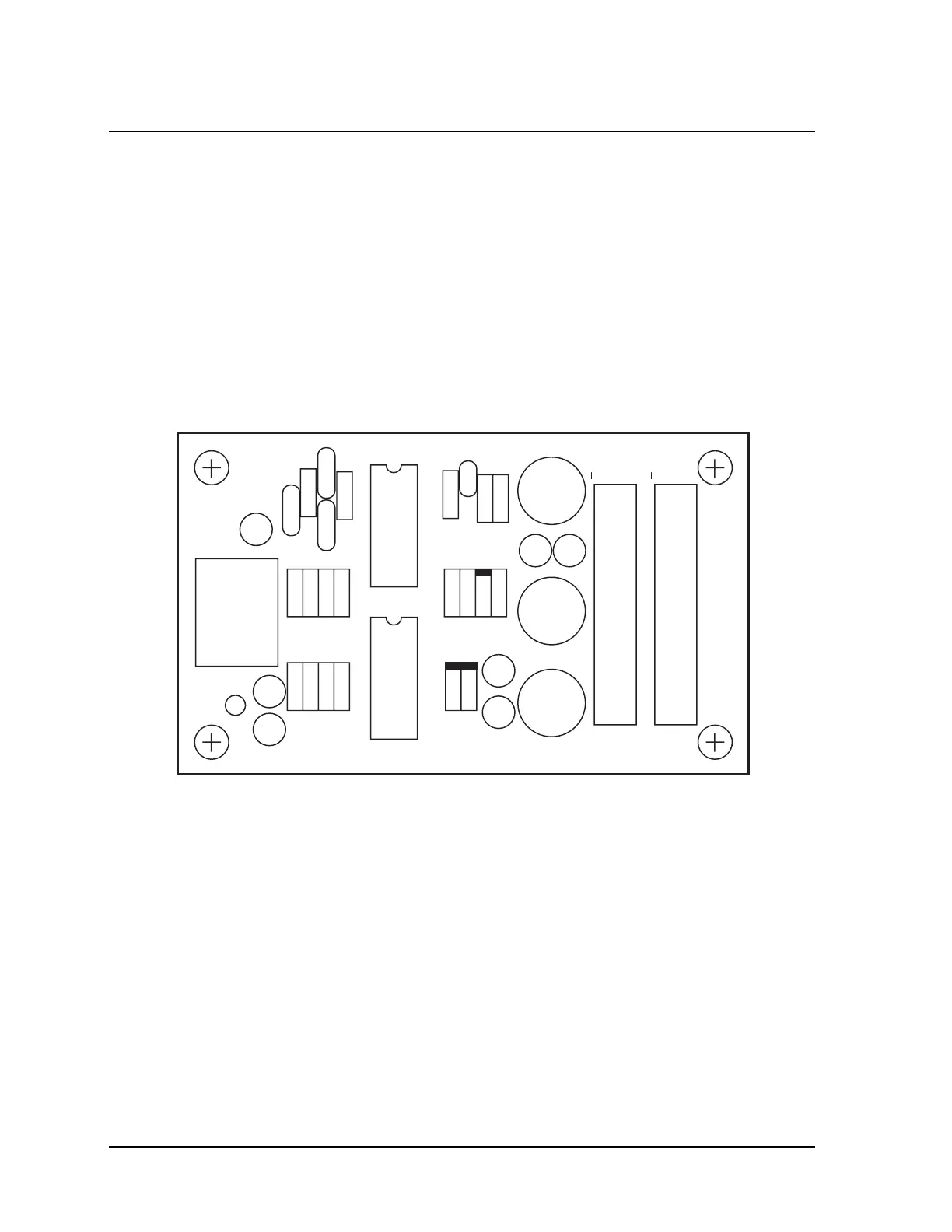
Figure E-2. Order Wire Board Component Layout