MDS 05-2415A01, Rev. A FIELD TESTS & ADJUSTMENTS 4-15
Data Deviation
1. With the transmitter still keyed (SW1 Closed), increase the deviation by rotating
R168 clockwise to cause the frequency to shift down from the assigned center
frequency by 1.6 kHz ± 75 Hz.
R
M
If Remote Maintenance is installed, set R168 to its full-clockwise position
and use the ID / DD / INCD / DECD commands to set the downward frequency
shift to 1.6 kHz. The ID / DD commands increment/decrement the deviation
in single steps while the INCD / DECD commands make larger jumps by
adding a space and a number to the command. (Example: INCD_4 to increase
the deviation by four steps out of 100.) When finished, type RMST to store
the setting.
2. Set the TXD line high (SW2 Closed). Observe the carrier frequency shifting up 1.6
kHz ± 75 Hz from the assigned center frequency. If it does not, alternately adjust the
TX Frequency adjustment on the TCXO and R168, checking both high and low
frequencies for equal 1.6 kHz shifts.
Note—There is some interaction between R168 and the TX Frequency adjustment on
the TCXO. If the shift is equal in both directions, but exceeds 1.6 kHz, it may be
necessary to turn the deviation down slightly and repeat this step. Continue to
alternately adjust R168 and the TX Frequency adjustment on the TCXO until equal
1.6 kHz shifts are obtained.
3. Set RTS and TXD low (SW1 and SW2 Open).
4. Set S1-3 on the modem to ON. This generates a data test pattern of 101010.
5. Set RTS high (SW1 Closed).
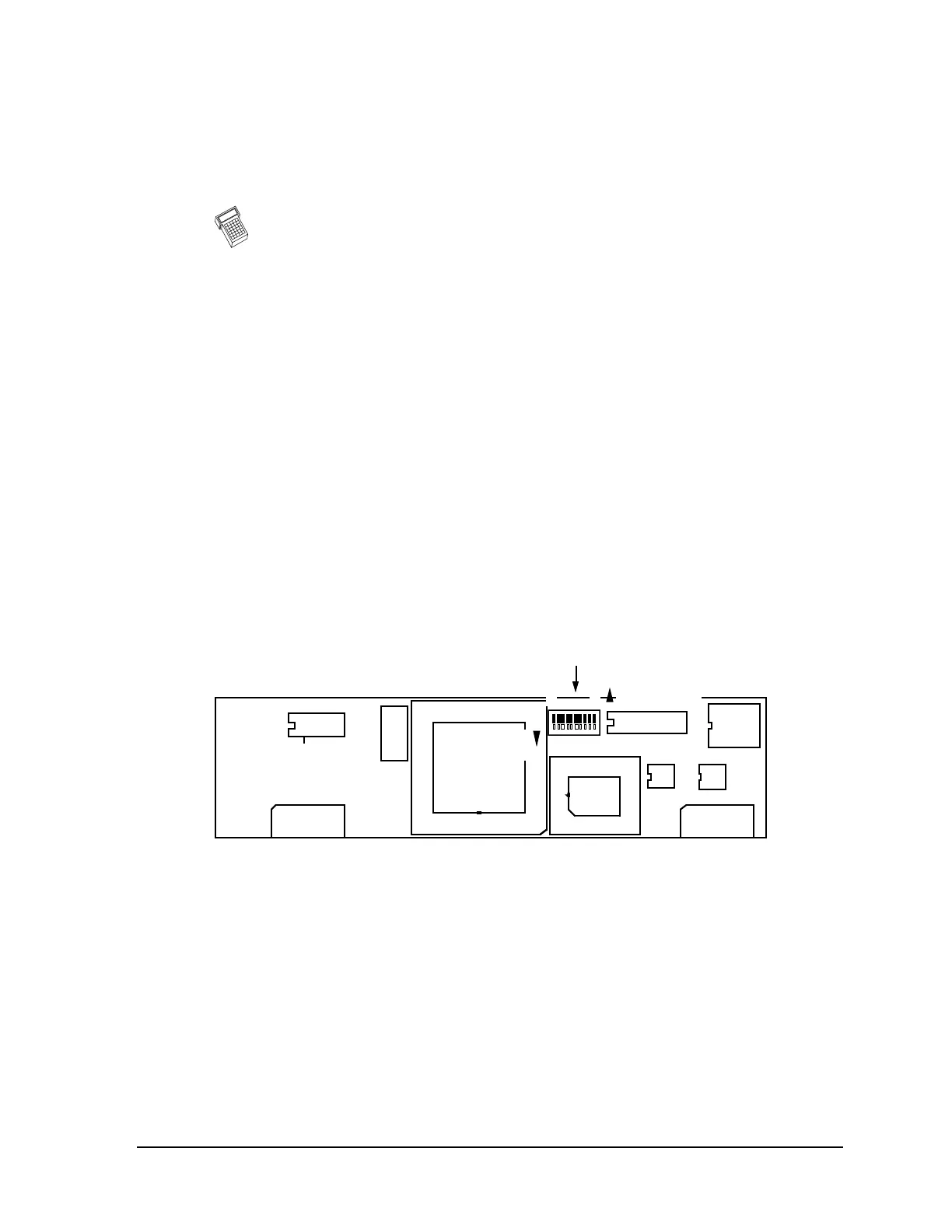
P8 P6
S1
CONFIGURATION
U6
U5
8 1
OFF (OPEN)
CLOSED
U3
Pin 3
ON
Figure 4-5. 4800 BPS FSK Modem; MDS P/N 03-1831A01
See Table B-1 in Appendix B for details on switch settings.
6. Adjust the HF Audio Compensation control, R179, if necessary, to produce 2.7 kHz
±75 Hz deviation as measured on the service monitor.
7. Set RTS low (SW1 Open) and turn OFF S1-3 on the modem.
8. Set the service monitor to generate a –60 dBm (225 µV) on-channel signal with a
1 kHz tone at 2.5 kHz deviation.
9. Connect an oscilloscope set to a 5 ms timebase to U3 Pin 3 on the modem. Adjust
R25 (Receive Audio Level) on the transceiver’s motherboard for a waveform
showing a 0.7 to 0.75 Vp-p sinewave riding on 2.5 Vdc.