MDS 05-2415A01, Rev. A FIELD TESTS & ADJUSTMENTS 4-9
If an in-line wattmeter is not available, the HHT can be used to obtain a rough
indication of the reflected power from the antenna system. Use FPWR to measure
forward power, and RPWR to measure the reflected power. The calculated VSWR can
be read using the VSWR command.
NOTE
The built-in power output and VSWR metering functions are
provided for the convenience of service personnel for making
quick checks of the radio’s performance. They are not
substitutes for calibrated test equipment.
4. Dekey the transmitter and remove the directional wattmeter from the antenna circuit.
VCO Lock Voltage Adjustment
In order for the radio to switch quickly between transmit and receive, the VCO range
capacitor is adjusted so that the lock voltage does not change between transmit and
receive modes. This adjustment requires monitoring the lock voltage with a DC voltmeter
on the transceiver motherboard or on the HHT using the LV command if the Remote
Maintenance Module is installed.
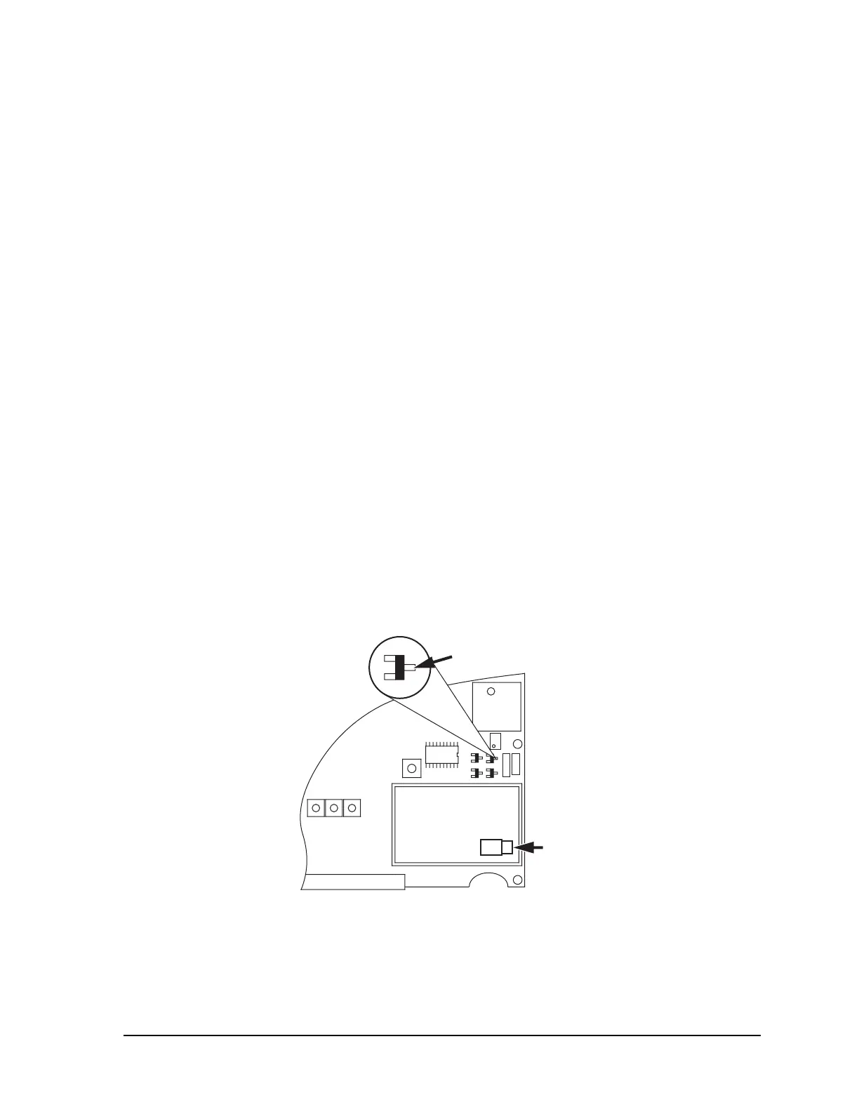
1. Place voltmeter at test point shown in Figure 4-3 or use the HHT to measure the
VCO lock voltage. The voltage should be between 2 and 7 Vdc.
2. Key the radio with the KEY command.
3. Monitor the voltage. The nominal voltage is not important, it should not vary more
than one tenth of a volt between transmit and receive modes.
4. If the voltage difference is greater than one tenth of a volt, adjust the VCO RANGE
capacitor C247, on the transceiver PC board until the lock voltage is the same (± 0.1
Vdc) in the transmit and receive mode. C247 is available through the shield of the
VCO sub-assembly.
VCO LOOP
VOLTAGE
TEST POINT
VCO
ASSEMBLY
SHIELD
C247
VCO RANGE
(THRU SIDE OF
SHIELD)
Figure 4-3. VCO Lock Voltage Test Point
This completes the basic tests of the MDS 4310 Transceiver.