MDS 05-2415A01, Rev. A INSTALLATION 2-3
To install the unit:
1. Choose a location to allow easy access to the fasteners so that the entire unit can be
readily removed for service or replacement, yet allows viewing of the LED
indicators on the front of the case.
2. Fasten the brackets to the mounting surface with a 1/4 inches (M6) bolt, screw, or lag
screw (fasteners not provided) through the four holes in the mounting bracket.
3. If mounting surface is uneven, use three fasteners instead of four to prevent warping
of the mounting bracket.
INTERFACE
KL TX RX
DC IN
DC IN
ANTENNA
OL
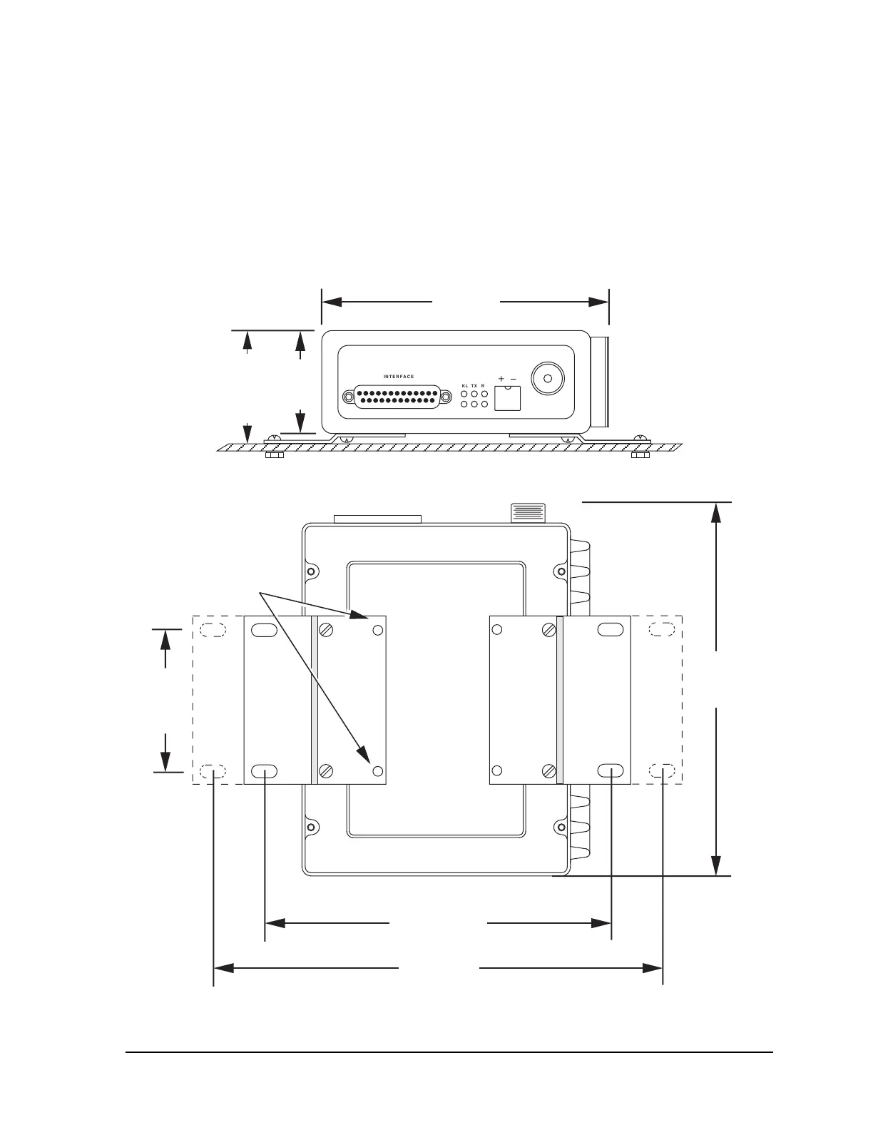
2.0 in.
51 mm
2.25 in.
57 mm
5.6 inches
143 mm
Figure 2-1. Mounting Dimensions—Front View
MOUNT BRACKETS WITH
THESE TWO HOLES FOR
ALTERNATE MOUNTING
6.75 inches
171 mm
8.5 inches
216 mm
7.25
inches
184 mm
2.75 in.
70 mm
USE ONLY
#6-32 x 5/16 INCH
SCREWS
Figure 2-2. Mounting Dimensions—Bottom View