MDS 05-2415A01, Rev. A PROGRAMMING AND DIAGNOSTICS 3-15
supporting a standard RS-232 interface can be used. The software commands for PC or
ASCII terminal control are identical to those listed for the HHT. (See Table 3-2.)
The communications settings for a PC or ASCII terminal must be as follows:
• Bit rate = 1200 bps.
• Number of data bits = 8, 1 stop bit
• No parity
• Full duplex mode
• Caps Lock enabled
Cable Wiring for a PC or ASCII Terminal
CAUTION
When connecting a PC or ASCII terminal to the MDS 4310
Transceiver, use only the required pins specified below. Do
not use a straight DB-25 to DB-25 cable wired pin for pin.
The use of improper cables may cause equipment damage.
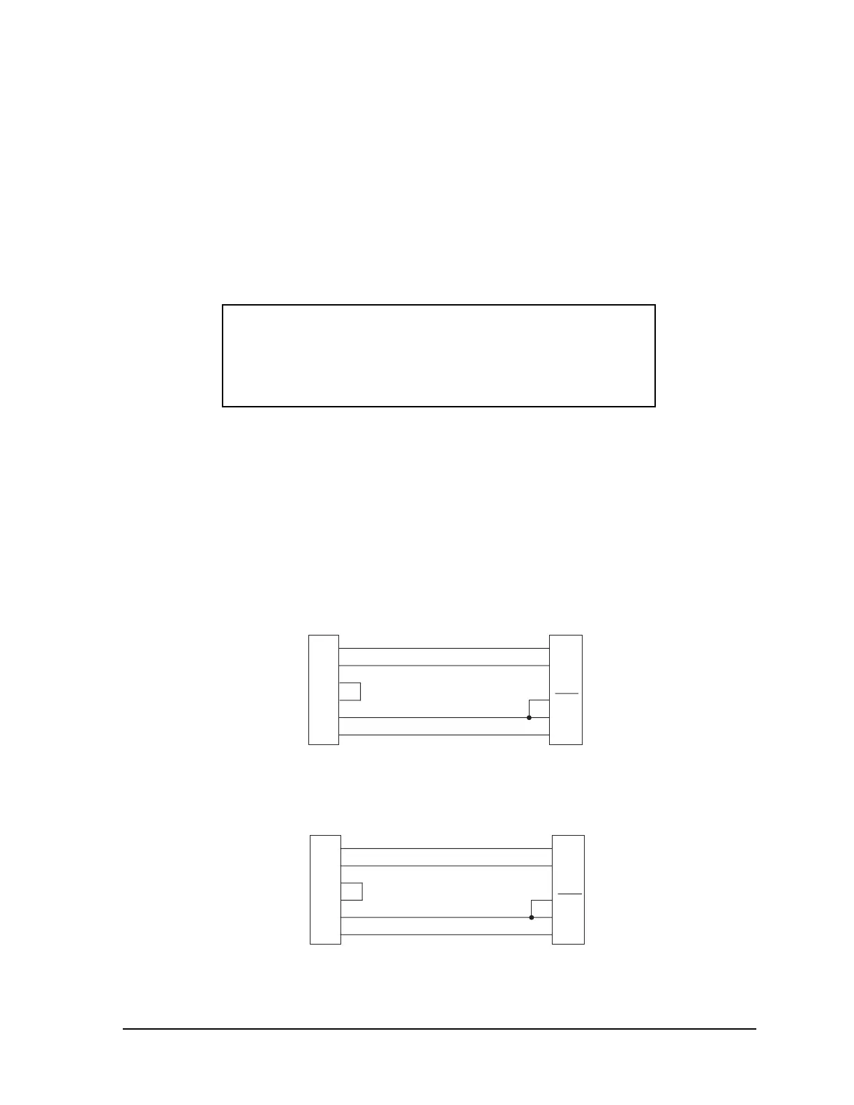
The cable connecting the PC or terminal to the transceiver must connect the TXD, RXD,
DSR and signal ground pins (DB-25 INTERFACE connector pins 2, 3, 6 and 7) as shown in
Figures 3-5 and 3-6. Pin 23 can be be connected to ground to automatically open the
diagnostic channel. If the PC or terminal is to be used for purposes other than diagnostics
or programming, do not connect Pin 23.
NOTE
A transceiver equipped with an internal modem can transmit
when connected to a PC, because of activation of RTS. Ensure
that the
ANTENNA connector has a 50 ohm termination on it
before proceeding.
COMPUTER DB-9
RADIO DB-25
3
2
7
8
5
1
TXD
RXD
RTS
CTS
GND*
DCD
TXD
RXD
GND*
DSR
FEMALE MAL
* Signal Ground
2
3
7
6
23
OPEN
Figure 3-5. DB-9 to DB-25 Interface Cable Wiring
COMPUTER DB-25 RADIO DB-25
2
3
4
5
7
8
TXD
RXD
RTS
CTS
GND*
DCD
TXD
RXD
GND*
DSR
FEMALE MALE
* Signal Ground
2
3
7
6
23
OPEN
Figure 3-6. DB-25 to DB-25 Interface Cable Wiring