Service Manual, 2016-12
33 / 47
10.Circuit description10.1 Power Supply
The AC input power is reduced in voltage by SMPS control chip and filtered off wave by the
inductance-capacitance filter, then output the DC 12V power which will mainly power the relay
that controls strong current. Relay is used to control the strong current loaded switches of
compressor, ice maker and defrost heater. The DC 12V power will output stable 5V electricity
after passing through the adjustor 7805, to power for the main control chip and thus monitor the
temperature changes in refrigerator. DC12V through the DCDC regulator chip TPS5403, output
stable 3.3V voltage to the wifi module supply power
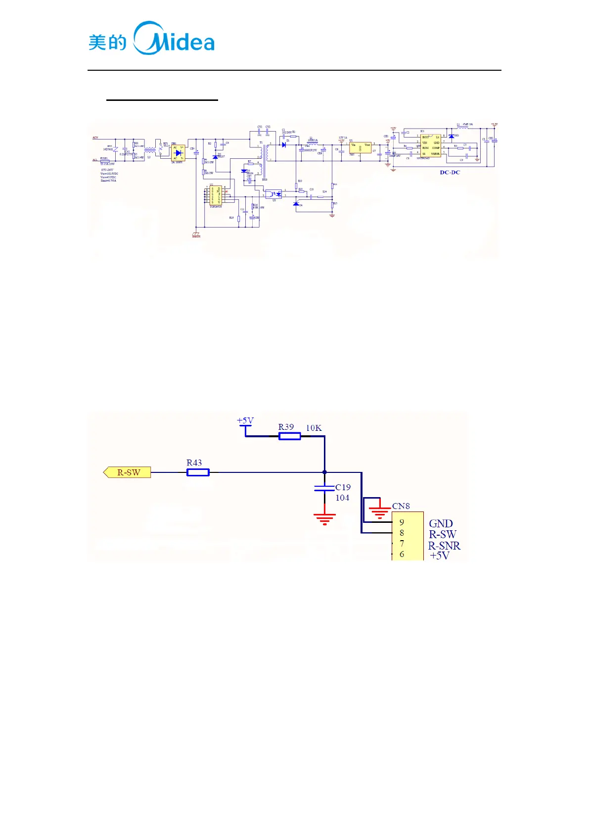
10.2Door trip test circuit
5V voltage cross the R39 and come to the main control chip with high level, at this time, the
door close. When the door open, the door switch off, 5V voltage is connected with GND through
R39, the chip detects the low level. The main chip acquire the state of door open and off by
detecting the low and high electrical level. When the state acquired, the main chip controls as
follows,
when the door open, the LED lamp on, the fan close. When the door close, the LED lamp off, the
fan starts. When the door open, the LED lamp doesn’t on, the fan still works check the door switch
first.
 Loading...