Part
6
-
Diagnosis and Troubleshooting
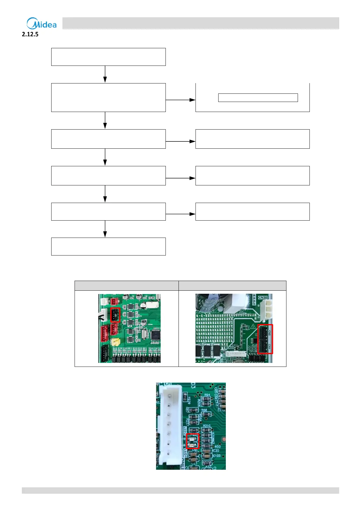
Communication wire from outdoor main
PCB CN26 to inverter module CN8/CN9 is
loosened.
1
Reconnect the communication wire.
Both LED1 and LED2 on inverter module
are off when power on.
2
Check the power supply circuit.
3
Replace the outdoor main PCB, is the
malfunction solved?
Replace the inverter module
Notes:
1. Communication wire from outdoor main PCB CN26 to inverter module CN8/CN9.
Communication port CN26 on outdoor main PCB
Communication port CN8/CN9 on inverter module
2. LED1/2 on inverter module
3. Check the power supply for the compressor inverter module, the normal voltage L2 and N (CN4/CN6) 198v-242V.