English-17
004-1055-00
TP210 Rev. A
© 2013 Midmark Corp. | 60 Vista Drive Versailles, OH 45380 USA | 1-800-643-6275 | 1-937-526-3662 |
[Revised: 2/17/16]
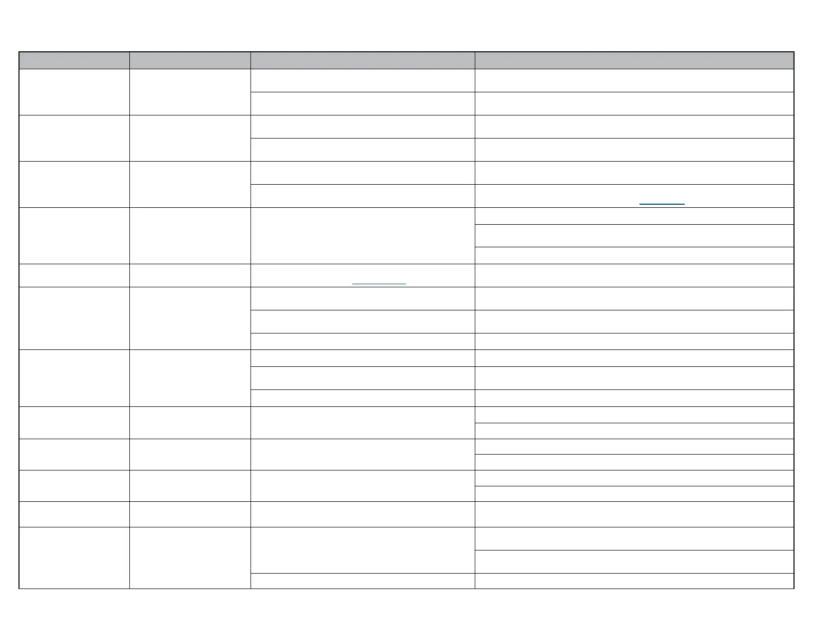
ID Code 01 (Machine Control Board) - continued
Error Code Error Denition Probable Cause Correction
10
Low Voltage 5 VDC
Loose connection.
Check all connections between Machine Control Board and
Power Supply PC Board.
Board Malfunction.
If LED (D-24) is illuminated, replace Machine Control PC Board.
If LED (D-24) is not illuminated, replace Power Supply PC Board.
11
Low Voltage 12 VDC
Loose connection.
Check all connections between Machine Control PC Board and
Power Supply PC Board.
Board Malfunction.
If LED (D-25) is illuminated, replace Machine Control PC Board.
If LED (D-25) is not illuminated, replace Power Supply PC Board.
12
Low Voltage 48 VDC
Loose connection.
Check all connections between Machine Control PC Board and
Power Supply PC Board.
Board Malfunction.
If LED’s (D-21 & D-22) are illuminated, replace Power Supply PC Board.
If LED’s (D-21 & D-22) are not illuminated, test Power Toroid
13
Temperature Out of Range Board Malfunction.
Disconnect power cord for at least ve seconds, then plug back in.
Remove power for ve minutes to allow Machine Control PC Board to cool,
then reapply power. Check if Power Supply PC Board is overheating.
Replace Power Supply PC Board if overheating continues.
14
Control Lockout
Control Lockout is activated.
Refer to: Control Lockout
Press and hold the Stop and Back Down buttons simultaneously for two seconds.
You will hear a single “Beep” to indicate control lockout is disabled.
15
Rotation Locked Out
Rotation brake switch detected pressed during power-up.
Disconnect power cord for at least ve seconds, then plug back in.
Ensure brake pedal is not depressed during power up.
Loose wire connection.
Check and secure wire connections at J12 on Machine Control PC Board
and rotation brake switch.
Rotation brake switch(es). Test / replace switch(es).
16
Treatment Pan Out
Treatment pan not in the stowed position. Push treatment pan all the way in.
Loose wire connection.
Check and secure wire connections at J6 on Machine Control PC Board
and treatment pan switch.
Treatment Pan switch. Test / replace switch.
17
Communication Error to
Motor Control
Message failure.
Error goes away by itself.
Disconnect power cord for at least ve seconds, then plug back in.
18
Communication Error to
Motor Control
Communication failure.
Error goes away by itself.
Disconnect power cord for at least ve seconds, then plug back in.
19
Communication Error to
Motor Control
Communication failure.
Error goes away by itself.
Disconnect power cord for at least ve seconds, then plug back in.
1A
Flashing
None Normal Operation. No action required.
1A
Continuously Illuminated
Communication Error to
Motor Control
Loose wire connection.
Check and secure wire connections at J3 on Power Supply PC Board
and J13 on Motor Control Hub PC Board.
Check and secure wire connections at J16 on Machine Control PC Board
and J14 on Motor Control Hub PC Board.
Power Supply PC Board fuse(s) blown. Test / Replace F3 & F4 fuses on Power Supply PC Board.
 Loading...