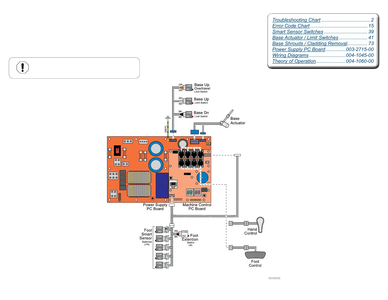
Troubleshooting Chart .................................... 2
Error Code Chart .......................................... 15
Smart Sensor Switches ................................ 39
Base Actuator / Limit Switches ..................... 41
Base Shrouds / Cladding Removal............... 73
Power Supply PC Board ...............003-2715-00
Wiring Diagrams ...........................004-1045-00
Theory of Operation......................004-1060-00