English-52
004-1055-00
TP210 Rev. A
© 2013 Midmark Corp. | 60 Vista Drive Versailles, OH 45380 USA | 1-800-643-6275 | 1-937-526-3662 |
[Revised: mo/dd/yr]
J14
J13
J12
J11
J10
J8
J7
J6
J4
J3
J2
F3
F2F1
J9
J5
J1
TPD1
TPD2
TPD3
TPC1
TPC2
TPC3
TPB1
TPB2
TPB3
J15
TPA
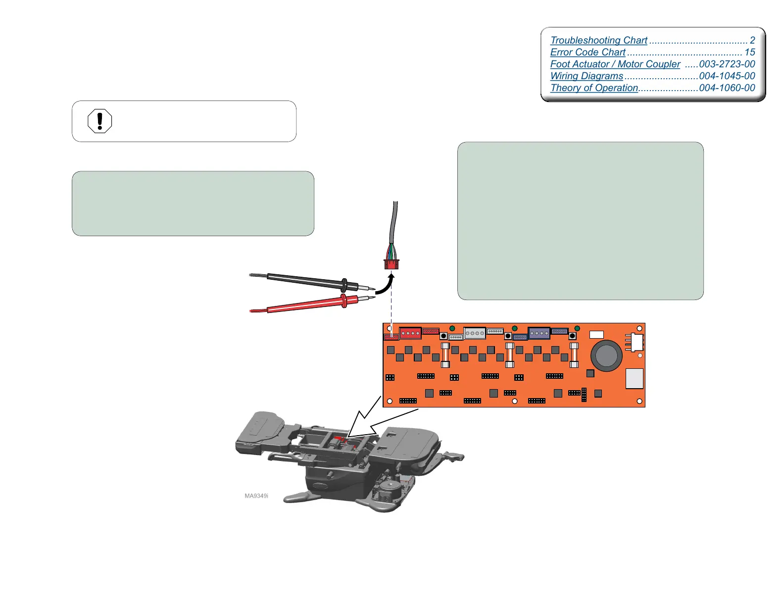
Foot Actuator Motor Resistance Test
Motor Control Hub PC Board
Troubleshooting Chart .................................... 2
Error Code Chart .......................................... 15
Foot Actuator / Motor Coupler .....003-2723-00
Wiring Diagrams ...........................004-1045-00
Theory of Operation......................004-1060-00
Troubleshooting Chart .................................... 2
Error Code Chart .......................................... 15
Foot Actuator / Motor Coupler .....003-2723-00
Wiring Diagrams ...........................004-1045-00
Theory of Operation......................004-1060-00
Equipment Alert
Anytime actuator wires are disconnected,
the table must be calibrated.
Step 1:
A) Disconnect power to the table.
B) Disconnect foot actuator from J2 on PC Board.
C) Set multimeter to Ohms to check resistance.
Step 2:
A) Place the Red meter probe on the Black wire,
and the Black meter probe on the Blue wire.
B) Place the Red meter probe on the Black wire,
and the Black meter probe on the Green wire.
C) Place the Red meter probe on the Black wire,
and the Black meter probe on the White wire.
If any of the readings are less than two Mega Ohms
after three seconds, the motor is defective.