English-68
004-1055-00
TP210 Rev. A
© 2013 Midmark Corp. | 60 Vista Drive Versailles, OH 45380 USA | 1-800-643-6275 | 1-937-526-3662 |
[Revised: mo/dd/yr]
J4
J1
F1
F2
F3
F4
J2 J3 J4 J5
J8
J9 J10 J11
J6
J12
J3
J5
J7
J6
J1
115V
J4
J1
F1
F2
F3
F4
F5
J2 J3 J4 J5
J8
J9 J10 J11
J6
J12
J3
J5
J7
J6
J1
115V
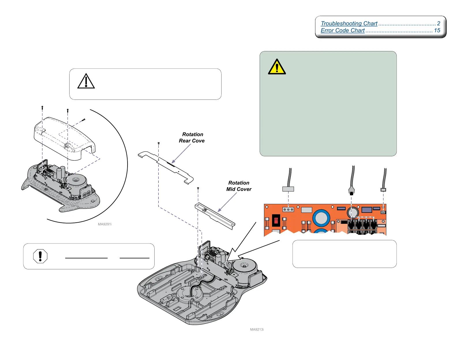
Rotational Base Brake System - continued
Separating Upper & Lower Base Castings - continued
Note
J2 thru J8 on Machine Control PC Board
are interchangeable.
Rotation
Mid Cover
Rotation
Rear Cover
Procedure continued on following page...
Equipment Alert
The wire connections and wire routing
must be put back in original locations.
WARNING
Disconnect the table power cord before
performing this step.
Step 5:
A) Remove three screws and PC Board cover.
B) Remove two screws and rotation mid cover.
C) Remove two screws and rotation rear cover.
D) Disconnect wire connections J1 and J4 from
Power Supply PC Board.
E) Disconnect wire connection J2 from
Machine Control PC Board.
F) Disconnect Ground wire from upper base
casting (Not Shown).
Troubleshooting Chart .................................... 2
Error Code Chart .......................................... 15
Troubleshooting Chart .................................... 2
Error Code Chart .......................................... 15
PC Board
Cover
Caution
The table top / upper base is not secured once the
hub screws are removed. Hold onto the table when
performing the following steps.