English-70
004-1055-00
TP210 Rev. A
© 2013 Midmark Corp. | 60 Vista Drive Versailles, OH 45380 USA | 1-800-643-6275 | 1-937-526-3662 |
[Revised: mo/dd/yr]
Rotational Base Brake System - continued
Separating Upper & Lower Base Castings - continued
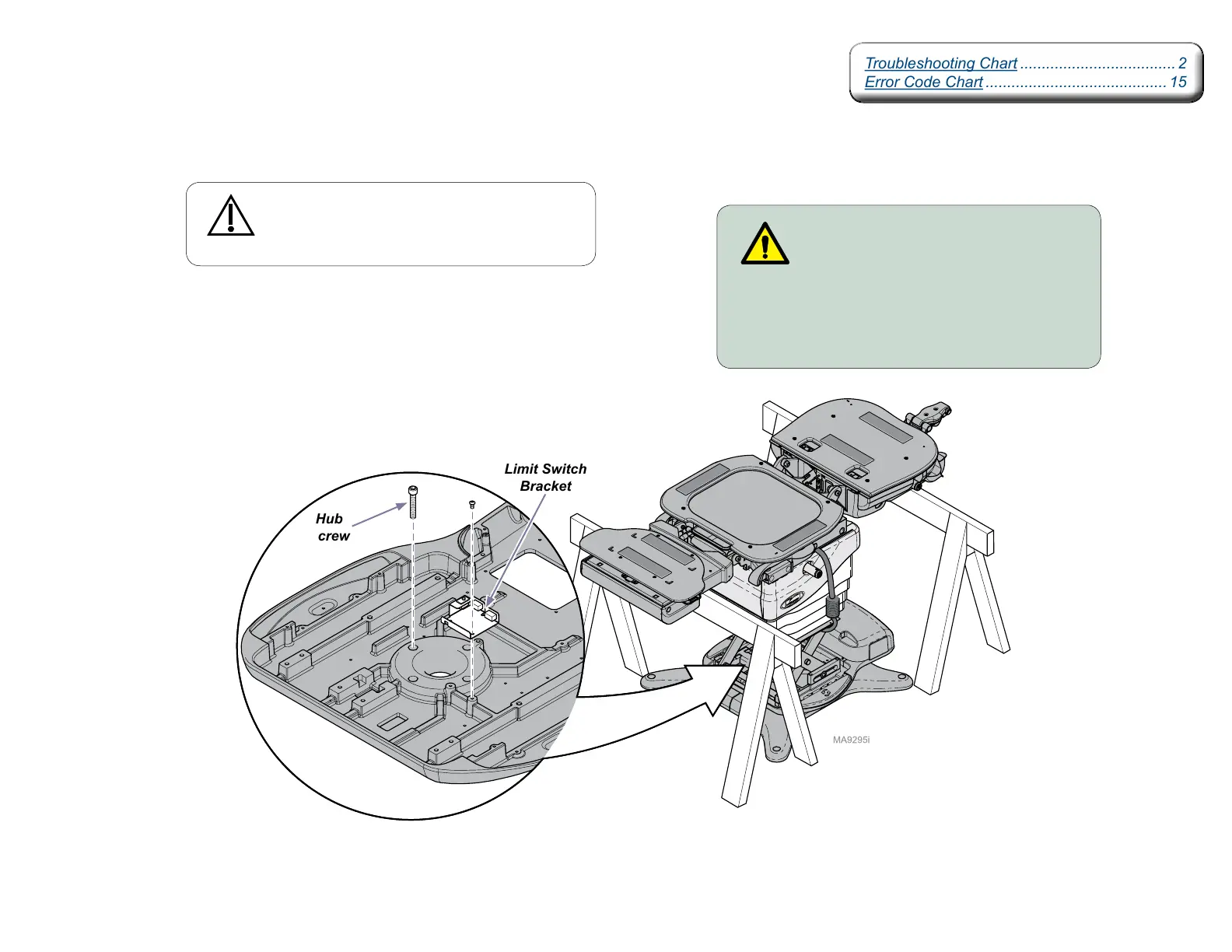
WARNING
Disconnect the table power cord before
performing the remaining assembly.
Step 7:
A) Install four hub screws and limit switch bracket.
Note: Reference steps 1 thru 5 to complete assembly.
Troubleshooting Chart .................................... 2
Error Code Chart .......................................... 15
Troubleshooting Chart .................................... 2
Error Code Chart .......................................... 15
Caution
The table top / upper base is not secured until the
hub screws are installed. Hold onto the table when
performing the following steps.
Limit Switch
Bracket
Hub
Screw