© Midmark Corporation 2016
conductor shielded lead wires. There is a 1Kohm (±10%) resistor embedded inside each lead wire. Together with the voltage
clamping circuit built into the ECG front end, the IQecg
®
provides the built-in defibrillation protection capability required by AAMI EC-
11 and IEC-60601.
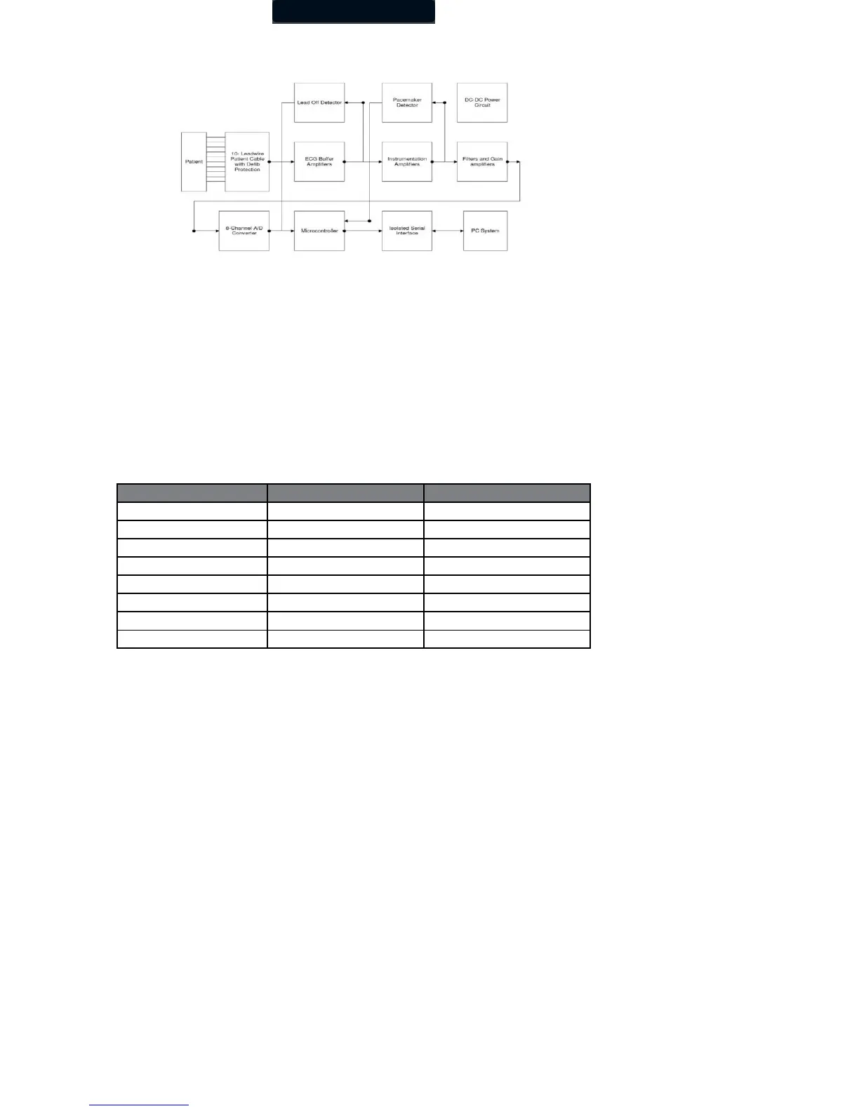
Figure 4 System Block Diagram
ECG Buffer Amplifiers
The patient ECG signals are first fed to the eight ECG buffer amplifiers. These buffer amplifiers provide high input resistance for the
patient interface, with low output resistance to the instrumentation amplifiers.
Instrumentation Amplifiers
There are eight differential instrumentation amplifiers used in the IQecg
®
, providing eight output signals, from
CH0 to CH7. Each differential amplifier has two inputs, with one positive and one negative.
The following table lists the positive and negative inputs for each channel.
The Wilson Center is a reference point combined with the three limb leads.
The purpose of the instrumentation amplifier is to provide a high Common Mode Rejection Ration (CMRR),
thereby rejecting common mode signals, such as 60 Hz line noise.
Filters and Gain Amplifiers
After the instrumentation amplifiers, the eight-channel ECG signals are passed into two stages of filters. The first stage consists of eight
first-order, high-pass filters with a cutoff frequency of 0.048Hz. The second stage consists of eight low-pass filters with a cutoff
frequency of 159Hz. The ECG signals are also amplified to match the AD converter’s input dynamic range of 0-2.5V.
There are eight test points provided on the PCB board. The test points are labeled as CH0, CH1, CH2, CH3, CH4, CH5, CH6, and
CH7. The signals measured on these test points are amplified with a gain of 125 and DC offset to 1.25Volt.
Analog to Digital Conversion
The AD converter used is the ADC12138 converter from National Semiconductor. The AD converter is 12-bit plus sign serial I/O A/D
converter with MUX and Sample/Hold. The amplified and filtered eight-channel ECG signals are passed to the eight-channel inputs of
the AD converter. The sampling rate for each channel is 500Hz. The digitized ECG data is sent to the microcontroller through the serial
interface.
Microcontroller
The microcontroller is a PIC16LC67 chip from Microchip Technology. This chip has 8Kx14 OTP, 33 I/O lines