Preva Installation/Service Manual, 00-02-1577, Revision E01
104
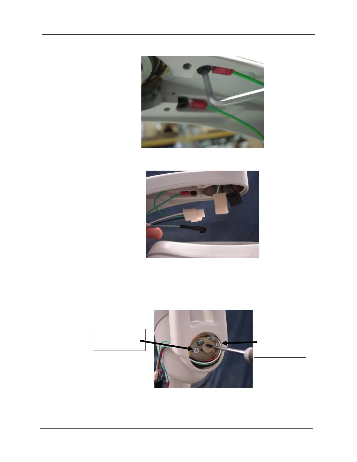
Figure 94
31. Re-attach the two ground cables that were removed in (Step 6.)
Figure 95
32. Connect the black and white connectors that were disconnected in (Step
5.)
Figure 96
33. To ensure correct operation and to prevent damage to the yoke cable
assembly perform the following steps:
33.1) Point the tubehead down.
33.2) Check that the large Phillips head screw is at the 9 o'clock
position and that there is a natural loop in the cable harness.
natural loop in the
screw at the 9