Preva Installation/Service Manual, 00-02-1577, Revision E01
127
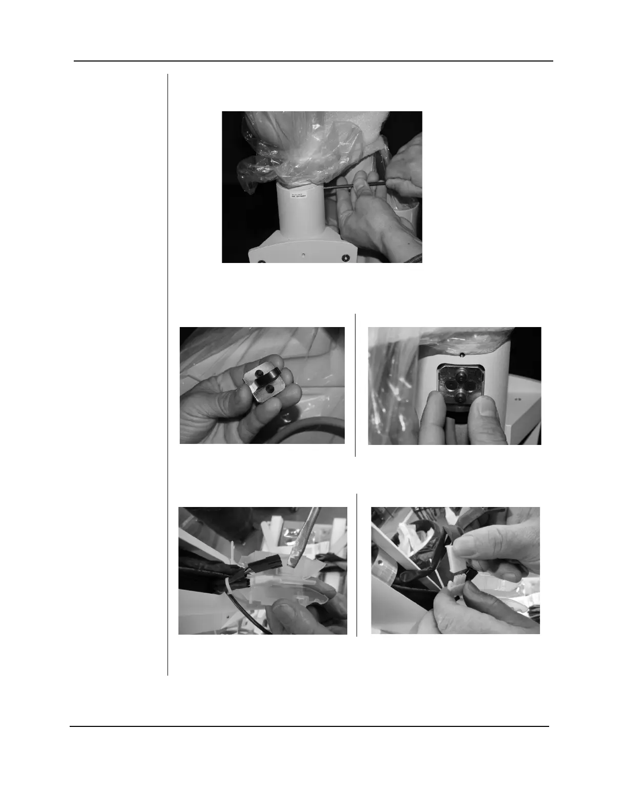
FIGURE 124
13. Secure the articulated arm assembly to the post with the
two column screws that were backed out in step 9.
FIGURE 127
FIGURE 128
14. Locate and install the articulating arm brake assembly. Install and adjust
by tightening to the point where the articulating arm does not drift when
the arm is pushed lightly.
FIGURE 129
15. Pry apart the Isolator containing the connectors for the cables. Connect
the power cables (white connectors).
16. Connect the feedback cables (black connectors). Insert cables into the
Isolator, one on each side of the divider and snap shut.