Preva Installation/Service Manual, 00-02-1577, Revision E01
129
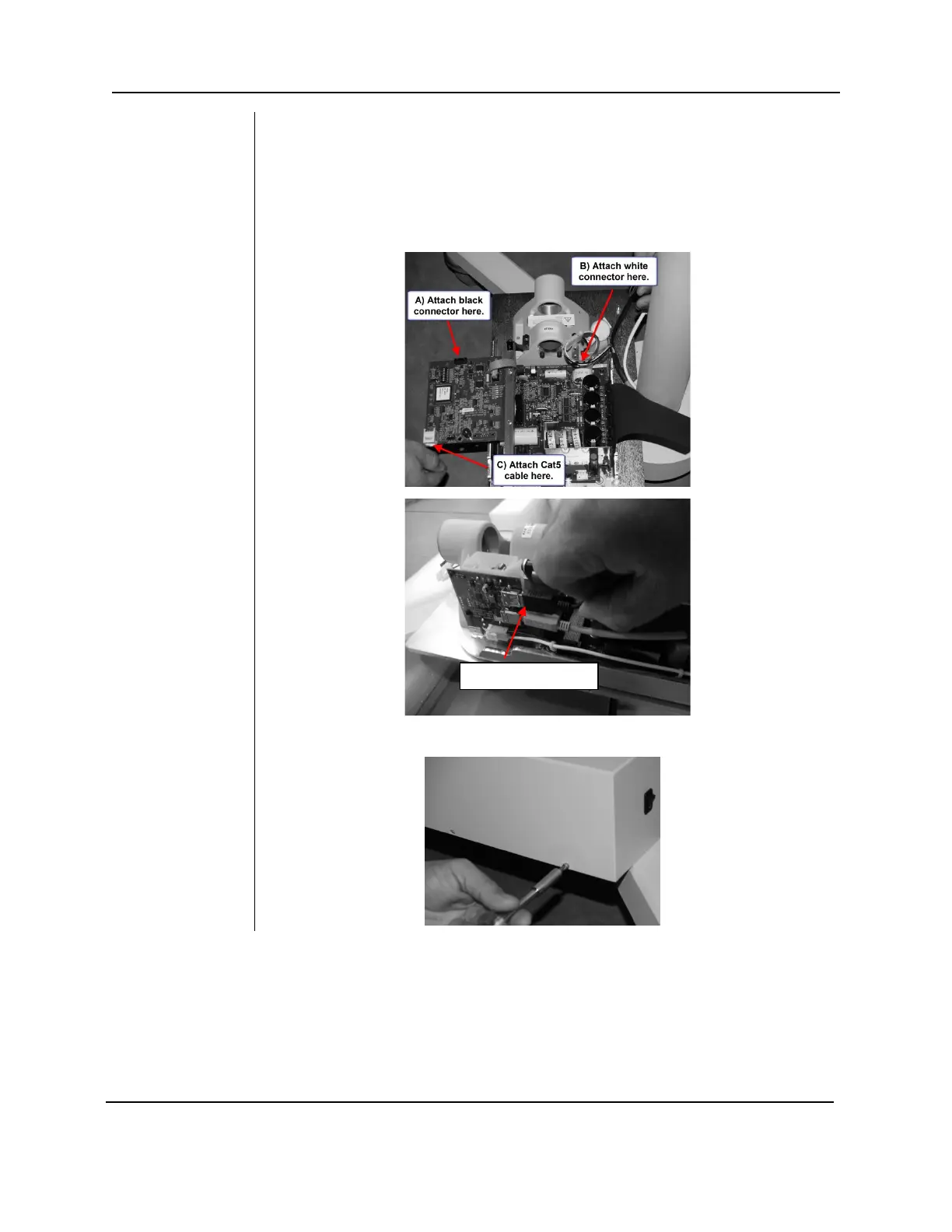
FIGURE 126
19. Remove the screw that locks down the Logic board. Swing out the Logic
Board and connect the three connections as shown below.
• A) Black connector (Feedback from tubehead)
• B) White connector (Power to tubehead)
• C) Cat5 (network cable)
• D) USB (for Sensor ready units)
FIGURE 138
20. Attach the control unit cover.