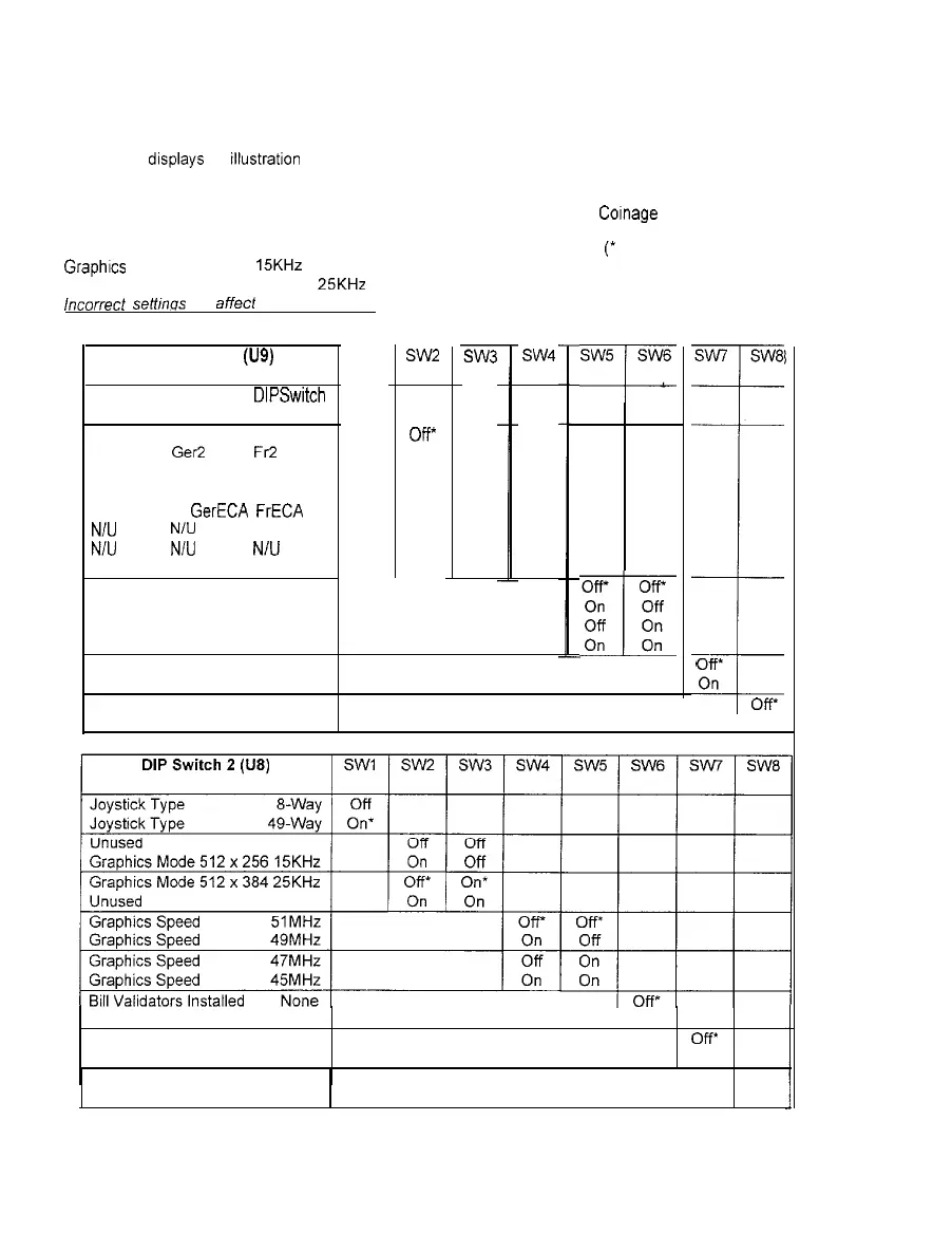
DIP-SWITCH TEST
The DIP-Switch Test allows operators to check the position of the two &position DIP-switches on the CPU
Board. The operator can also change the setting of any DIP-switch without removing the CPU cover.
To enter the test, use a joystick to select the DIP-switch Test and any control panel button to activate it.
The screen
drsplays
an illustratron of each switch block. Some switch positions may show as unused,
DIP-switches may be changed with the power on. Set any switch, then check the screen to verify that the
new setting is now enabled. Country switch settings have no effect if CMOS Cornage Control is set to On.
Refer to the charts for assistance in choosing the desired switch positions
(*
indicates factory defaults).
Graphrcs Mode 512 x 256 15KHz is best for most standard resolution video game monitors; the factory
default Graphics Mode 512 x 384 25KHz is correct for most medium resolution video game monitors.
incorrect setfinos will aMed other test results. Press any control panel button to exit the DIP-switch Test.
DIP Switch 1 (U9)
SW1
Coinage
Control
USA1
Gerl
DIPSwitch
CMOS
Frl
Off
On*
USA2 Ger2 FR
USA3
Ger3
Fr3
USA4 Ger4 Fr4
USAECA GerECA FrECA
N/U
N/U N/U
N/U N/U N/U
Free Play Free Play Free Play
USA
French
German
Unused
Unused
Unused
Power Up Test Loop One Time
Power Up Test Loop Continuous
SW2
off*
Off
Off
Off
On
On
On
On
OR
Off
On
On
Off
Off
On
On
SW4
Off’
On
Off
On
Off
On
Off
On
SW5 SW6
=L
Off’
off*
On Off
I
Off On
On On
SW7
SW8
T
I
*
Ofi*
On
off*
1 On
Bill Validators Installed One
1 On
Power Up Test Active OV
Power Up Test
Inactive
On
Test Manual
Off’
Mode Forced On
2-l 2