FUNCTION
WIRE COLOR
GKUlCl Black
Ground
Black
+SVDC Red
+SVDC
Red
-5VDC
YellW#V
+lZVDC
Orange
Key
N/C
Coin Counter 2
Brown-Red
Not Used
NIC
Speaker
-,
Lefl
Brown-Gray
Speaker
-,
Right
Brown-White
Video Green
Green
Video Sync
White
Service Credits
White-Gray
Slam Tilt
Black-Green
Coin 2 Black-Red
2 Start
Violet-White
Not Used
N/C
Not Used N/C
Not Used
NC
Not Used N/C
2 Jump/Tackle
Violet-Yellow
2 Pass/Change
Violet-Green
2 Turbo
Violet-Blue
Not Used
N/C
Not Used
NIC
-5V Ground
Yellow-Brown
Ground
Black
S”,
nFR StnF OF
ROARI
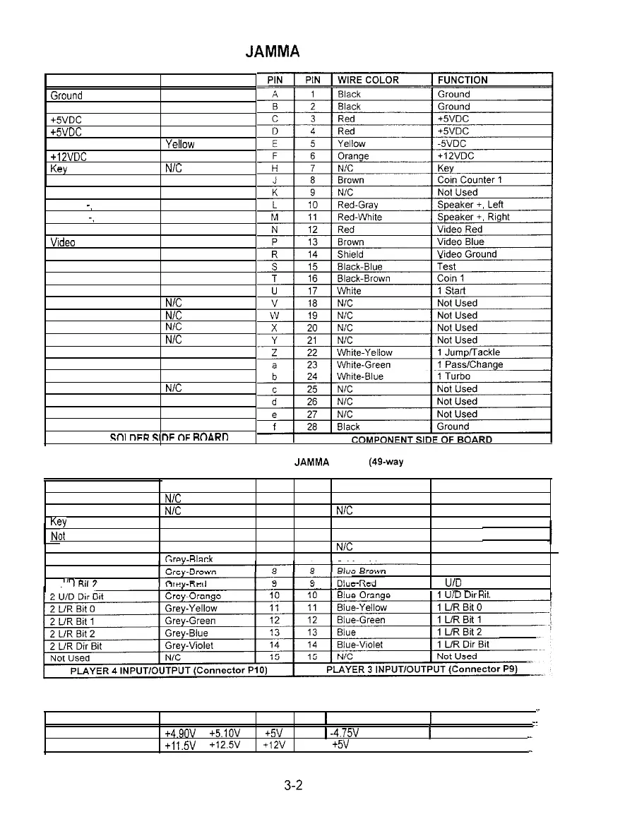
JAMMA Chart
Control Panel wires not part of the Main
JAMMA
Harness (49~way Joystick Cables)
2 Digital Ground
Not Used
Not Used
Y?Y
It Used
Not Used
2 U/D Bit 0
2 U/D Bit 1
2 ’
I’-
Black
N/C
N/C
N/C
N/C
N/C
Grev-Rlack
1 1
Black 1 Digital Ground
2 2 NIC Not Used
3 3 N/C
Not Used
4 4 NIC Key
5 5 NIC
Not Used
6
6 N/C Not Used
7 7 Blue-Black 1 U/D Bit 0
1 U/D Bit 1
1 U/D Bit 2
7it
D.C. Power Source Voltage Limits
.-
.
FUNCTION
RANGE LIMITS
ID
ID 1 RANGE LIMITS 1
FUNCTION
--
Digital Circuits
+4.9ov to +5.1ov +5v
-5V 1
-4.75V
to -5 25V 1 Audio, Lights
Audio. Disk Drive, DBV
+I
1.5V
to
+12.5V
+12v
NOTE: +5V is adjustable at the Power Supply
:
3-2