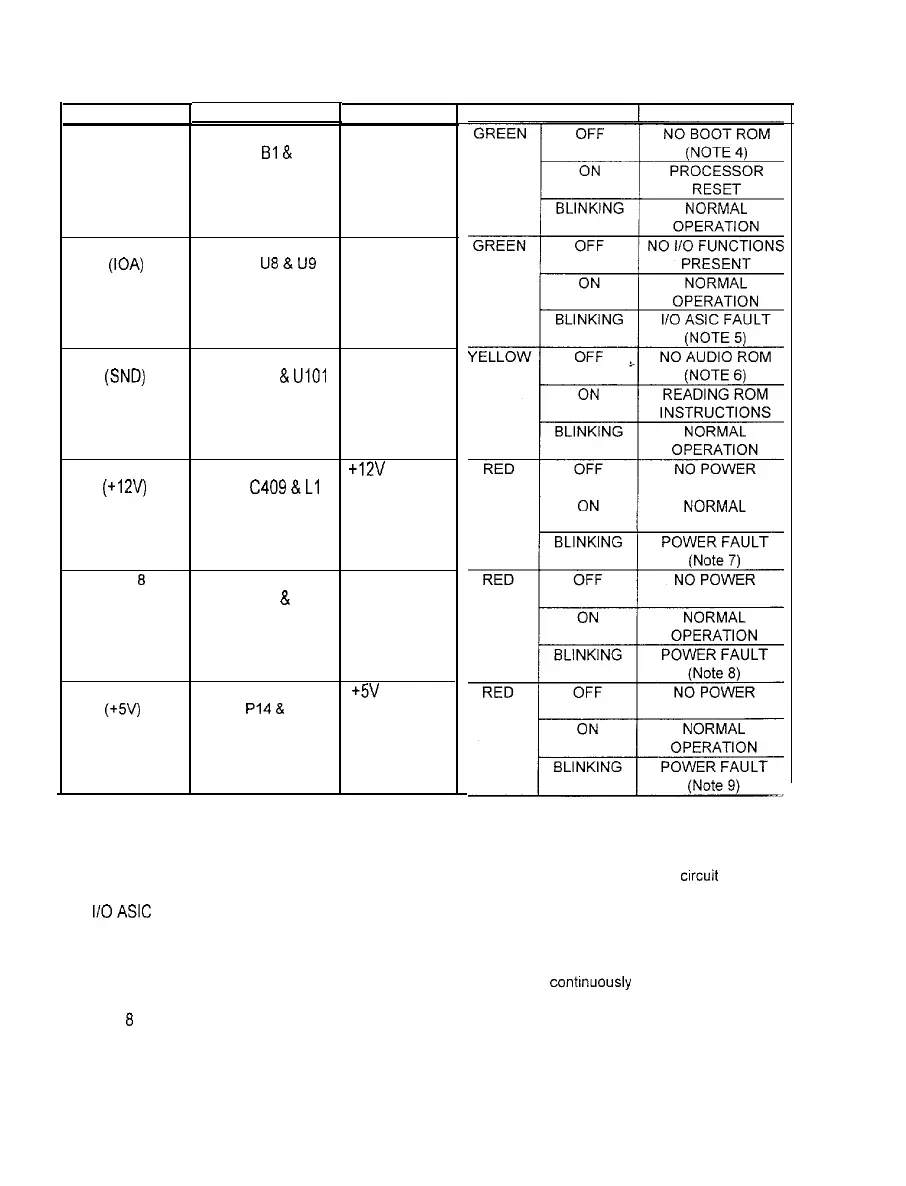
CPU BOARD LED INDICATOR STATUS CHART (continued)
DESIGNATION
LED 4
NOTES:
LED 5
(104
LED 6
(SW
LED 7
(+12v)
LED
6
(-5V)
LED 9
(+5V)
LOCATION
MIDDLE CENTER
NEAR Bl
&
S2
UPPERCENTER
NEAR
U6
&
US
UPPER LEFT
NEAR U95
&
UIOI
UPPER RIGHT
NEAR C409 & Ll
UPPER RIGHT
NEAR L2 & P4
UPPER RIGHT
NEAR PI4
&
R571
FUNCTION
INDICATOR
CONTROL
ACTIVITY
SOUND
ACTIVITY
+12V POWER
INDICATOR
-5V POWER
INDICATOR
+5V POWER
INDICATOR
COLOR 1 STATE
MEANING
OPERATION
4.
Boot ROM is only active in short bursts during start up. May appear very irregular durrng
crrcuit
reset.
5 110
ASIC is only active in short bursts during start up. Must be on continuously during game play.
6.
Sound is only active in short bursts during start up
Must be on continuously during game play.
7.
LED 7 monitors a regulated power supply voltage source. Must be on contrnuously at all times.
a
LED
8
monitors a regulated power supply voltage source. Must be on continuously at all times.
9.
LED 9 monitors a regulated power supply voltage source. Must be on continuously at all times.
3-8