MM571W / MM572W Installation Instructions 9
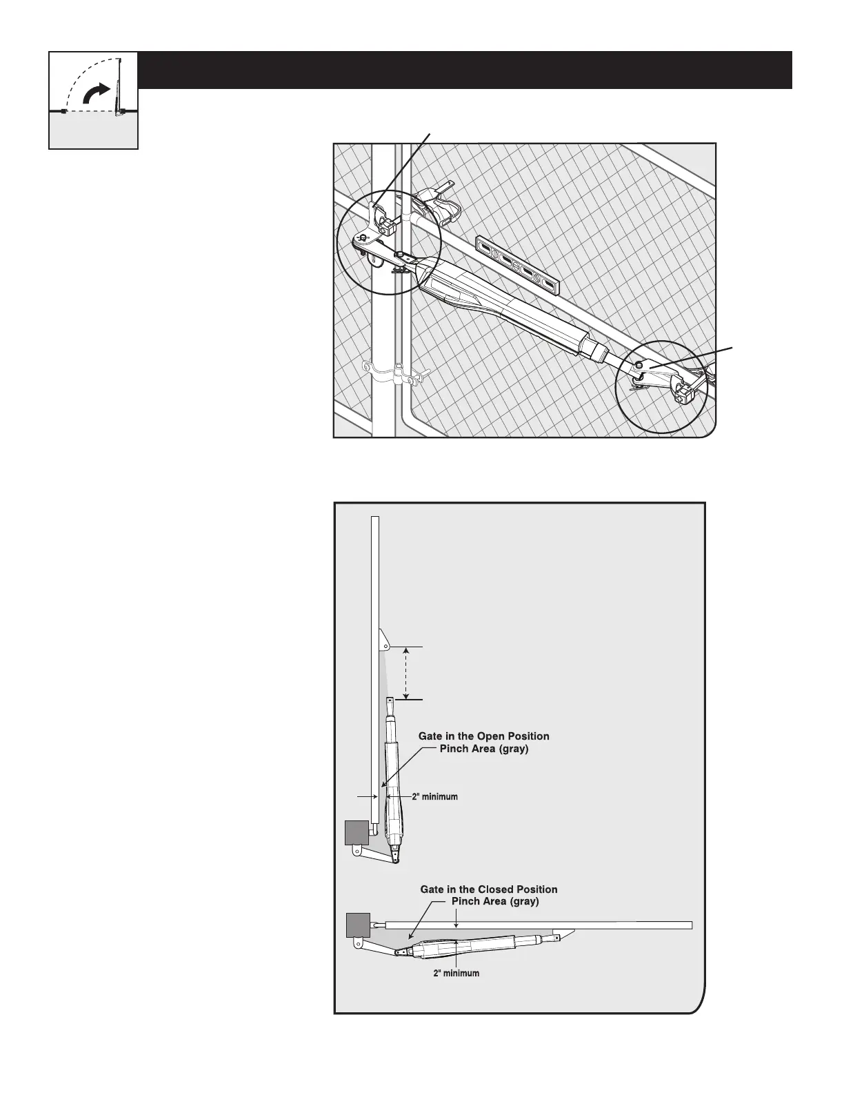
PUSH-TO-OPEN OPERATOR MOUNTING
L
e
v
e
l
horizontal
cros
s
me
m
be
r
L
ev
e
l op
e
ner
Gate in Closed Position
Gate Bracket
Post Bracket Assembly
Step 3
Step 4
● With the gate in the CLOSED
position, use clamps to secure the
operator to the gate post and center
cross member of the gate.
● Ensure that the operator is level.
● With the operator arm temporarily
secured to the gate, check to
ensure there is at least 2 inches
of clearance between the operator
arm and gate. (See illustration in
Step 4 below).
20” MAX
CLEARANCE DIAGRAM
● Disconnect the operator arm from the
gate bracket.
● While supporting the operator, swing
the gate and operator to the OPEN
position.
● Check for recommended clearances
and binding as shown.
● Ensure that the necessary arm stroke
does not exceed 20 inches.
● Make adjustments to the
mounting brackets to achieve the
recommended clearances.
TIP: Turning the pivot bracket over
gives more hole alignment options for
the gate post pivot bracket assembly.
Your Property