20 MM571W / MM572W Installation Instructions
Step 4
MM572 Installation - For dual arm installation, drill through one of the Alternate Access slots to install the
Transformer or Solar power wires.
C
GRN
WHT
BAT+
AUTO
CLOSE
RESET
PULL
STAGGER
WARNING
BAT–
GRN
WHT
BRN
ORG
BRN
ORG
RED
BLK
RED
BLK
COM
COM
CYCL
SAFE
EXIT
SHDW
AUX
V+
AUX
V-
LOCK
V+
LOCK
V-
CLOSE
EDGE
OPEN
EDGE
PRIMARY
SECONDARY
LOCK AUX
SW1
SW2
PUSH
12345
+
TERM6
GRN
WHT
BAT+
BAT–
GRN
WHT
BRN
ORG
BRN
ORG
RED
BLK
RED
BLK
AUX
V+
AUX
V-
PRIMARY
SECONDARY
SW1
SW2
TERM6
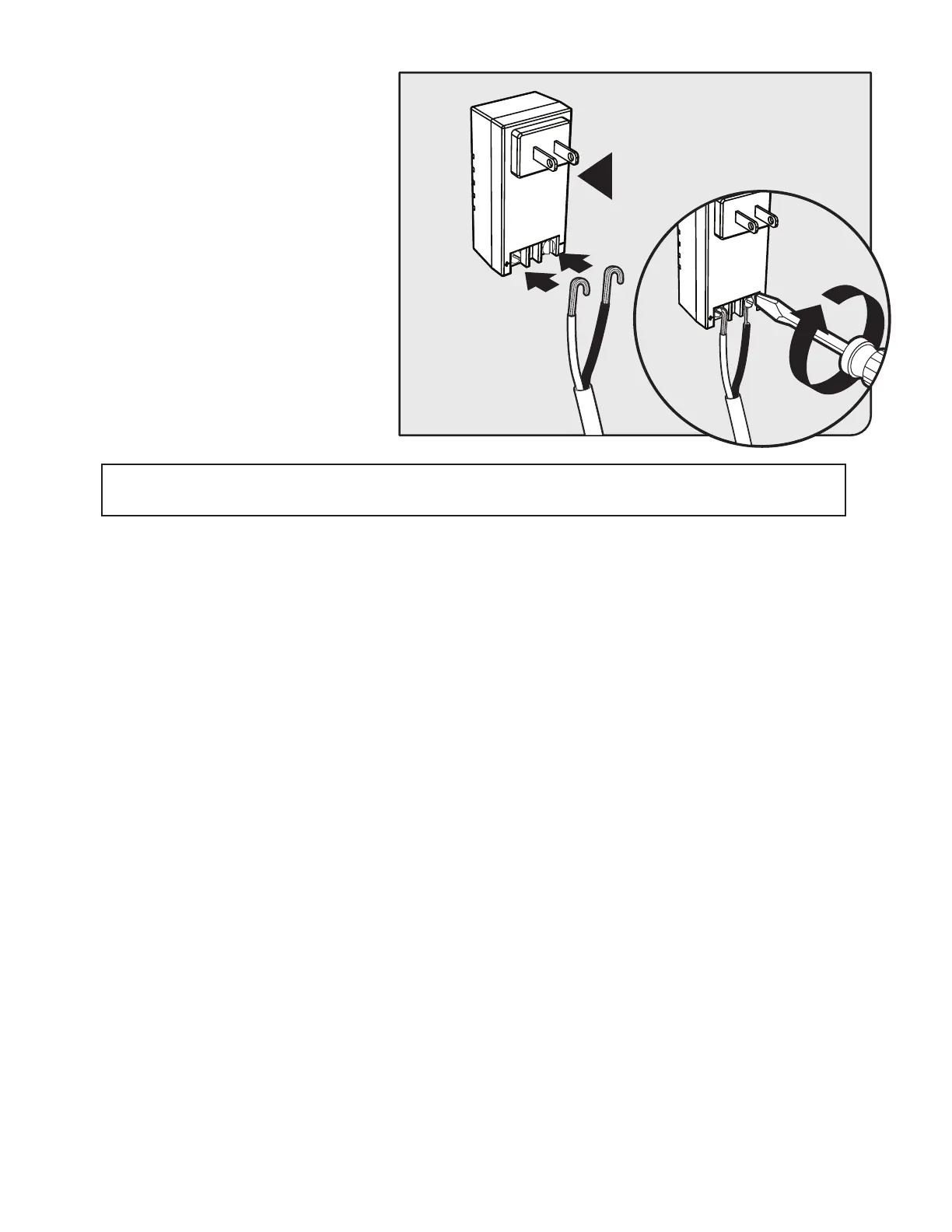
● From the other end of the low voltage wire,
strip 1/2” from both the RED and BLACK
wire.
● On the transformer, connect RED wire to
the screw terminal marked + and BLACK
wire to the screw terminal marked -.
● Plug the transformer into the selected
electrical outlet.
Note: Use of a surge protector is strongly
recommended.