OM-350 Page 12
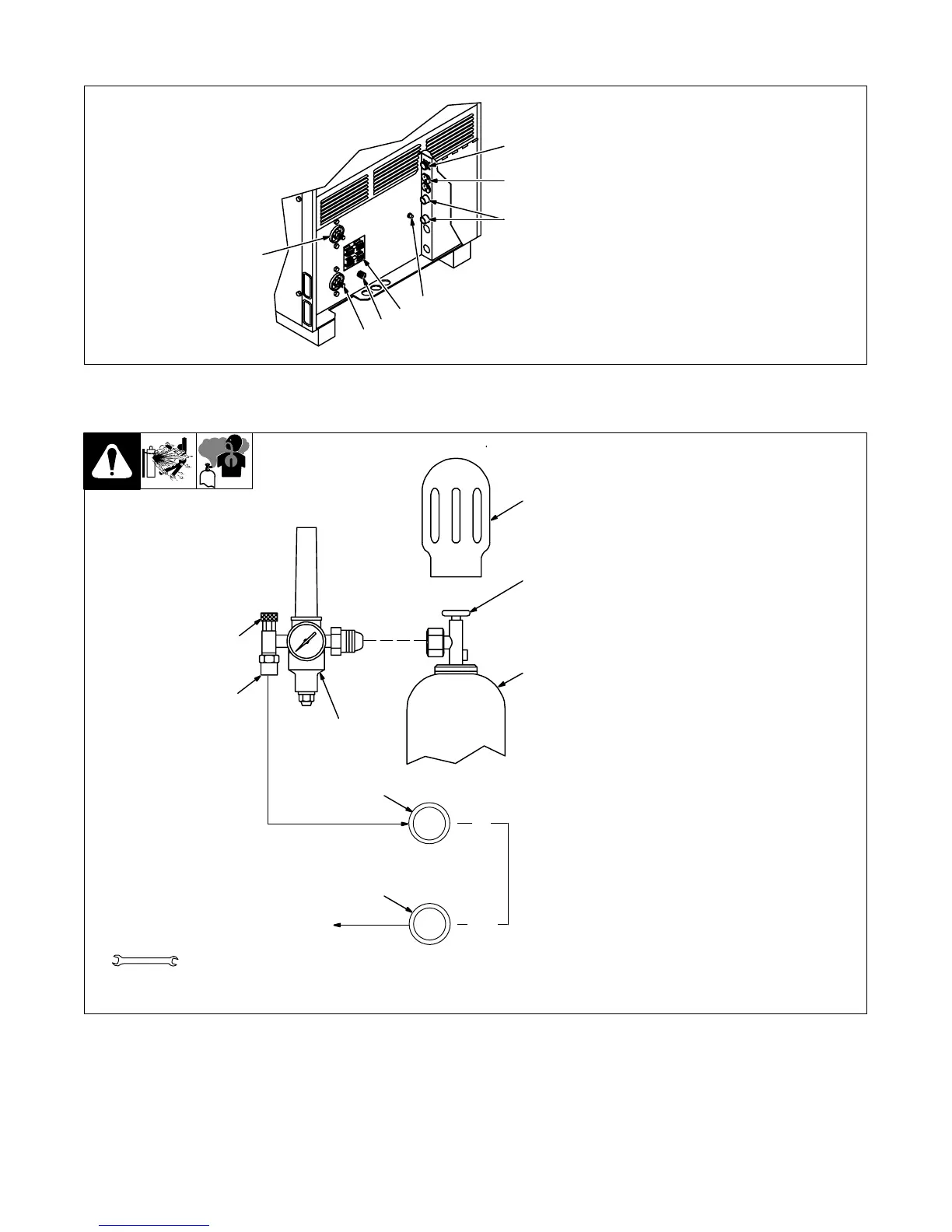
2-9. Lower Front Panel
Ref. ST-144 405-B
1 Work Output Terminal
2 Electrode Output Terminal
3 High Frequency Intensity
Control (See Section 3-9)
4 Spark Gaps (See Section 4-2)
5 Circuit Breaker CB1 (See
Section 2-11)
6 Gas Valve Fittings
7 115 VAC Duplex Receptacle
8 Remote Contactor And Cur-
rent Control Receptacle
1
2
3
4
5
6
7
8
2-10. Installing Gas Supply
Chain cylinder to running gear, wall,
or other stationary support so it
cannot fall and break off valve.
1 Cap
2 Cylinder Valve
Remove cap, stand to side of valve,
and open valve slightly. Gas flow
blows dust and dirt from valve.
Close valve.
3 Cylinder
4 Regulator/Flowmeter
Install so face is vertical.
5 Gas Hose Connection
Fitting has 5/8-18 right-hand
threads. Obtain and install gas
hose.
6 Flow Adjust
Typical flow rate is 15 cfh (cubic feet
per hour).
Make sure flow adjust is closed
when opening cylinder to avoid
damage to the flowmeter.
7 Gas In Fitting
8 Gas Out Fitting
The gas In and gas Out fittings have
5/8-18 right-hand threads.
Connect hose as shown.
Close access door.
ssb3.3* 5/94 – Ref. ST-158 697- / Ref. C-085 461
Tools Needed:
5/8, 1-1/8 in
4
5
6
1
2
3
Argon Gas
7
IN
OUT
8
GAS
To Torch





 To Next Page