OM-281138 Page 14
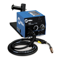
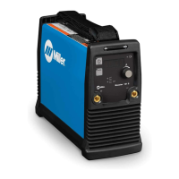
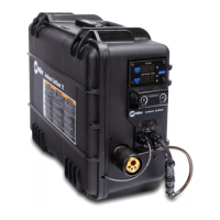
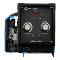
1 CV Welding Power Source
With 24 VAC Power
2 CV Welding Power Source
Without 24 VAC Power
3 115 Volts AC /24 Volts AC
Power Adapter
4 14-Pin Control Cord
5 Weld Cable (Required)
6 Work
5-2. Equipment Connection Diagrams
115VAC
Contactor
3
2
6
6
5
5
4
1
4
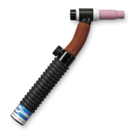
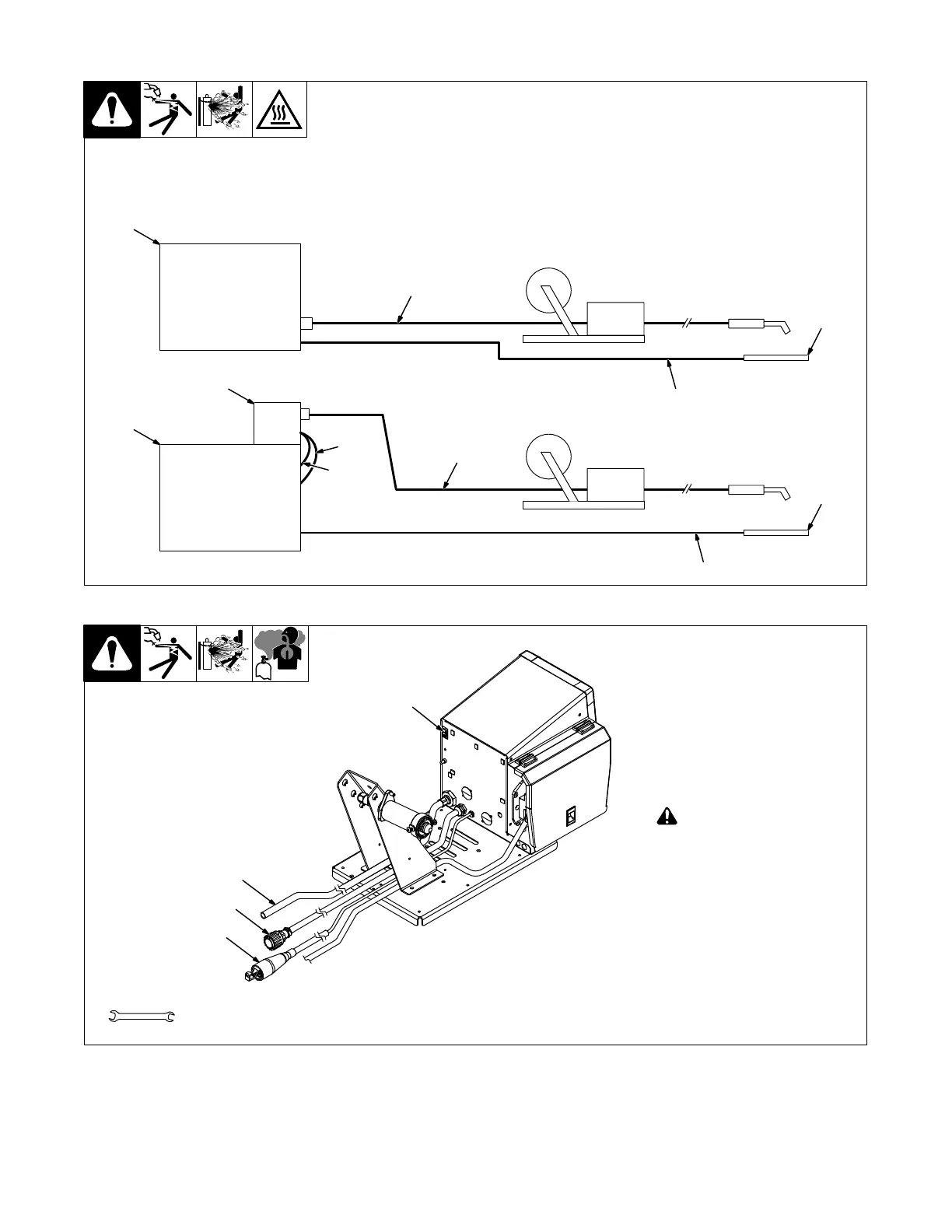
1 Gas Hose With 5/8-18 Right-
hand Thread Fittings
(Customer Supplied)
. Shielding gas pressure not to
exceed 100 PSI (689 kPa).
2 14 Pin Plug PLG2
Use plug to make connection to
welding power source.
3 Optional Volt Sense Lead
(Part Of Meter Option)
! Weld voltage is present at
voltage sensing clamp
when wire feeder and weld-
ing power source are on.
This condition exists even if
wire feeder lights and
meters are off.
Turn off wire feeder or weld-
ing power source before
handling or moving voltage
sensing clamp.
Connect to volt sense lead.
4 Power Switch
5-3. 14-Pin Plug, Shielding Gas And Optional Volt Sense Lead
281202-A
Tools Needed:
3
5/8, 11/16 in.
4
2
1
 Loading...