OM-281138 Page 16
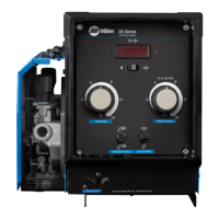
5-6. Optional Meter Circuit Board Settings
Ref. 240358-A
Tools Needed:
1/4 in.
1 Meter Circuit Board
2 DIP Switch S2
Set DIP switch S2 for type of
welding power source, and desired
wire feed speed display (see
illustration).
Reinstall wrapper.
12 3 45
12345
123 45
123 45
Or
Or
Meters/Minute
Inches/Minute
Digital Meter Display
Arc Voltage Sensing Using Voltage Sensing
Lead For Welding Power Source That Does
Not Support Pins F And H
Voltage Sensing Function
Arc Voltage Sensing Using Feedback From
Welding Power Source That Does Support
Pins F And H
1
2
X Means switch position does not affect
specified function.
.
Means switch must be in this position.
2
1
 Loading...