OM-281138 Page 15
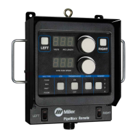
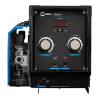
5-4. 14-Pin Plug Information
Pin* Pin Information
A
J
B
K
I
CLN
H
DM
G
E
F
A 24 volts AC with respect to pin G.
B Contact closure to A completes 24 volts AC contactor control circuit.
G Circuit common for 24 volts AC circuit.
C +10 volts DC output to remote control with respect to pin D.
D Remote control circuit common.
E 0 to +10 volts DC input command signal from remote control with respect to pin D.
F Current feedback; 0 to 10 volts DC, 1 V/100 A
H Voltage feedback; 0 to 10 volts DC, 1 V/10 arc volts
*The remaining pins are not used. Ref. S-0004-A
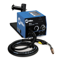
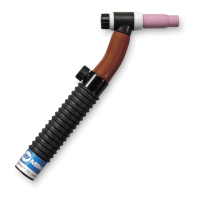
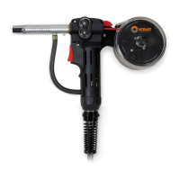
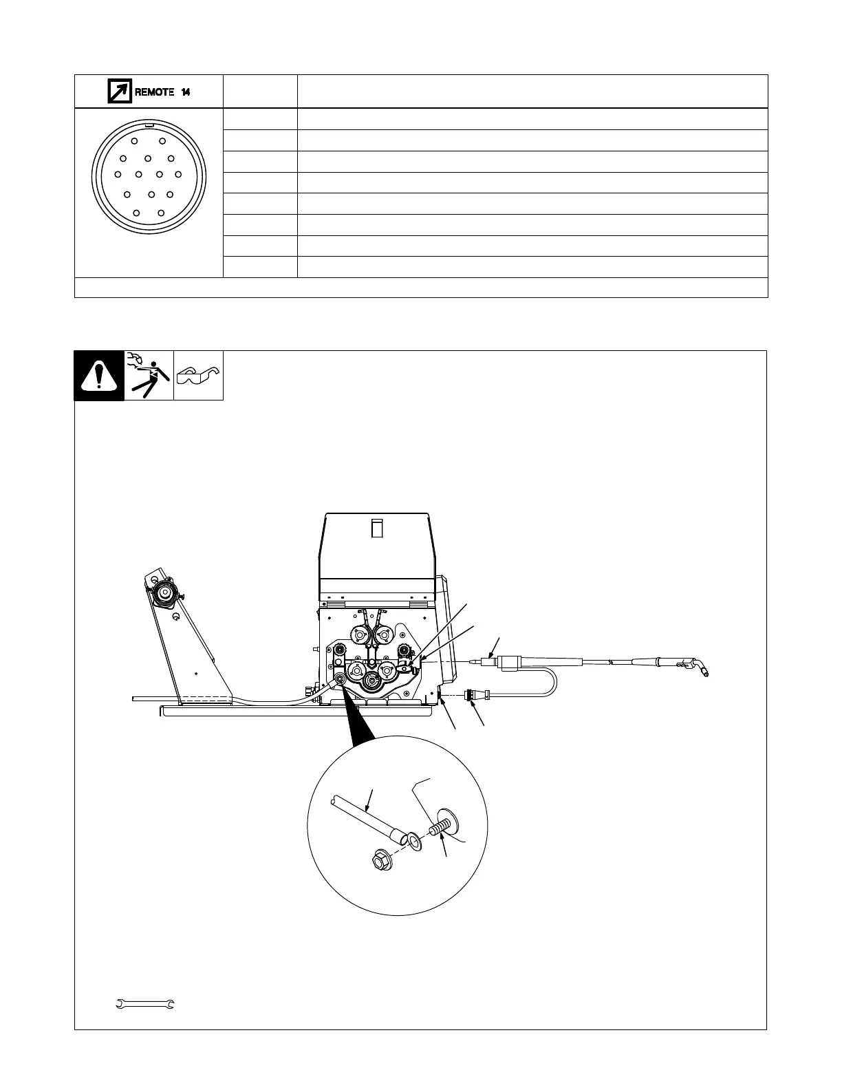
1 Gun Securing Knob
2 Gun Block
3 Gun Outlet Wire Guide
Loosen knob, insert gun into block.
Position outlet wire guide as close
as possible to drive rolls without
touching. Tighten knob.
4 Gun Trigger Plug
5 Gun Trigger Receptacle
6 Weld Cable Terminal
7 Weld Cable From Welding
Power Source
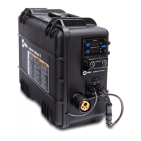
5-5. Connecting Welding Gun And Weld Cable
Ref. 281186-A
1
3
Tools Needed:
9/16, 5/8 in.
2
4
5
7
6
 Loading...