OM-404 Page 17
SECTION 5 – OPERATING WELDING GENERATOR
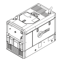
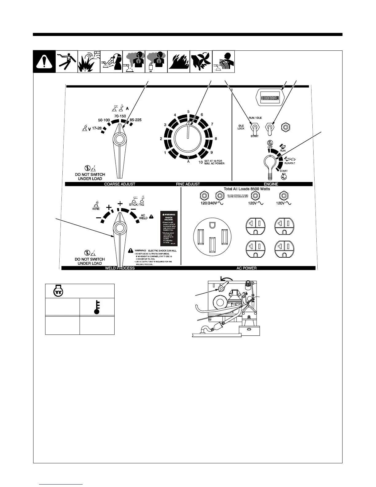
5-1. Front Panel Controls
Ref. 192 785 / Ref. 801 434
62
4
1 Engine Control Switch
Use switch to start engine, select speed, and
stop engine. In Run/Idle position, engine
runs at idle speed at no load, and weld/power
speed under load. In Run position, engine
runs at weld/power speed.
Place switch in Run position to operate
most GMAW equipment.
2 Glow Plug Switch (Optional)
If necessary, push switch up before start-up
(see table).
3 Idle Lock Switch
Use switch to lock engine in idle speed
during start-up. In Start position and Engine
Control switch in Run or Run/Idle, engine is
locked in idle speed. In Run/Idle position and
Engine Control switch in Run/Idle, engine
runs at idle speed at no load and weld/power
speed under load.
In Run/Idle position and Engine Control
switch in Run, engine runs at weld/power
speed.
To start: move idle lock switch and engine
control switch to Start. Release engine con-
trol switch when engine starts.
If the engine does not start, let engine
come to a complete stop before attempt-
ing restart.
Move idle lock switch to Run/Idle after
engine warms.
To stop: move engine control switch to Off.
4 Weld Process Selector Switch
Use switch to select type of weld output.
Use a positive (+) position for Direct Current
Electrode Positive (DCEP) and a negative
(–) position for Direct Current Electrode Neg-
ative. Use AC position for alternating
current.
5 Coarse Adjust Switch
Use switch to select weld amperage range
when Weld Process Selector switch is in
Stick/Tig position, or voltage range when
switch is in Wire position.
For best arc starts, use lowest amper-
age range possible.
6 Fine Adjust Control
Use control to select weld amperage (Stick/
Tig) or voltage (Wire) within the range se-
lected by the Coarse Adjust switch. Control
may be adjusted while welding. Weld output
would be 110 amps DC with control settings
as shown (50% of 70 to 150). Scale is for ref-
erence only.
7 Engine Hour Meter
8 Manual Shutoff Lever
Turn lever counterclockwise to stop engine
if engine control switch does not work.
1
75
8
t
0 s
10 s
20 s
70°F (21°C)
32°F (0°C)
–4°F (–20°C)
Glow Plug Time
Right Side
3
 Loading...