OM-216 869 Page 92
SECTION 13 − SETUP GUIDES FOR (SMAW) STICK WELDING
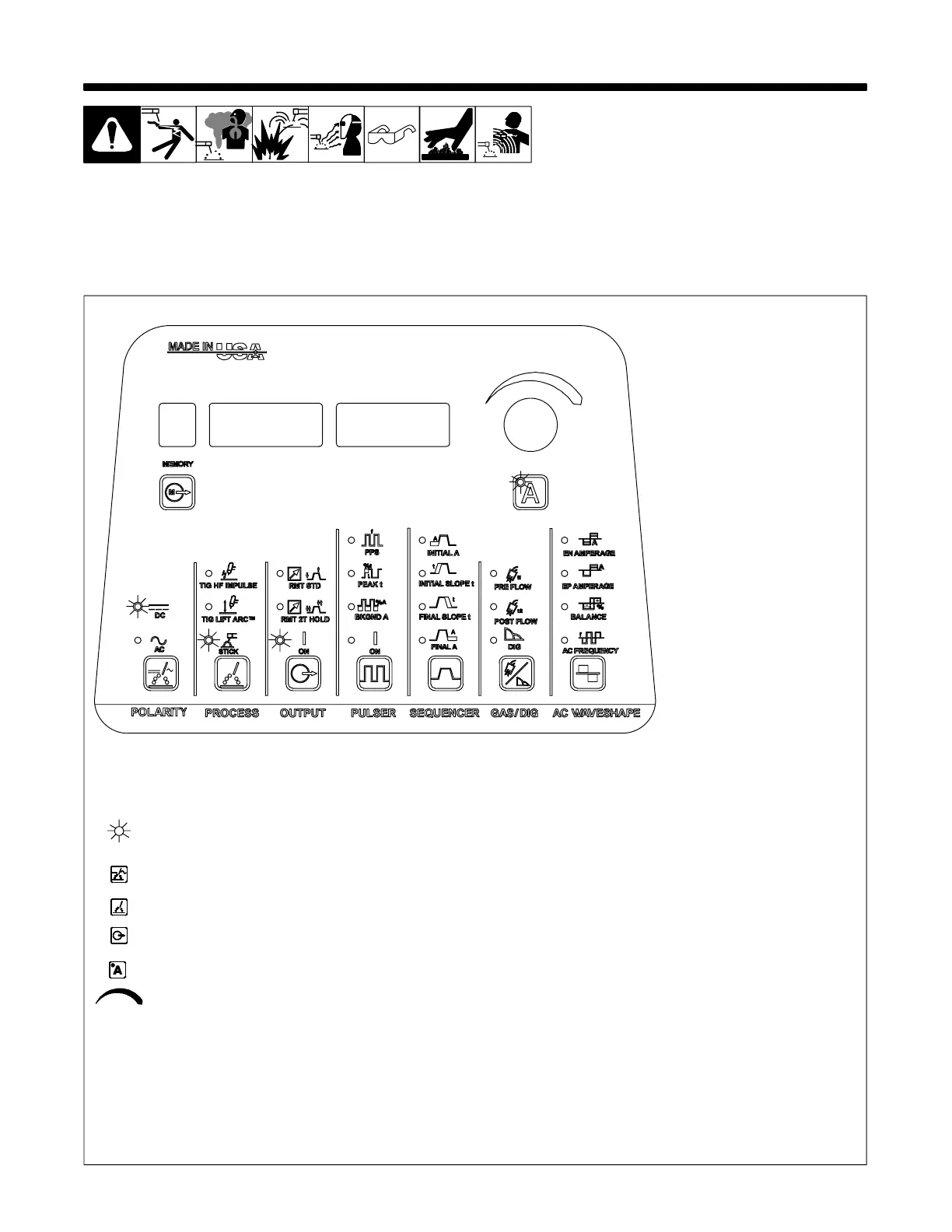
13-1. Front Panel Display For Stick DCEP (Direct Current Electrode Positive)
216 869-B
Some of the controls shown above may not be on your machine (Dynasty 350/700 illus-
trated).
Gray on nameplate indicates a Stick function (see Section 5-1 for description of con-
trols).
This symbol indicates which functions should be active for Stick DCEP (Direct Current Elec-
trode Positive) welding.
• Turn power on (switch located on rear panel)
• Press Polarity switch pad until DC LED is lit (Dynasty Models Only)
• Press Process switch pad until STICK LED is lit
• Press Output switch pad until ON LED is lit
• Press Amperage A switch pad until LED is lit
• Turn Encoder control to set desired amperage.
The ammeter displays the parameter for any of the following units of measure when they
are active: amperage, time, percentage, or frequency. The corresponding LED, located
directly below the ammeter, will also light up. The ammeter also displays actual amper-
age while welding.
 Loading...