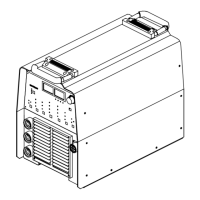
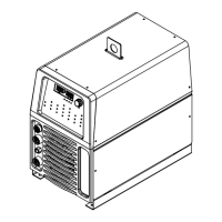
OM-216 869 Page 51
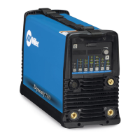
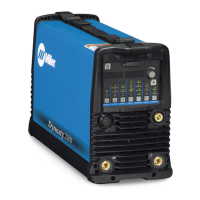
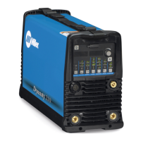
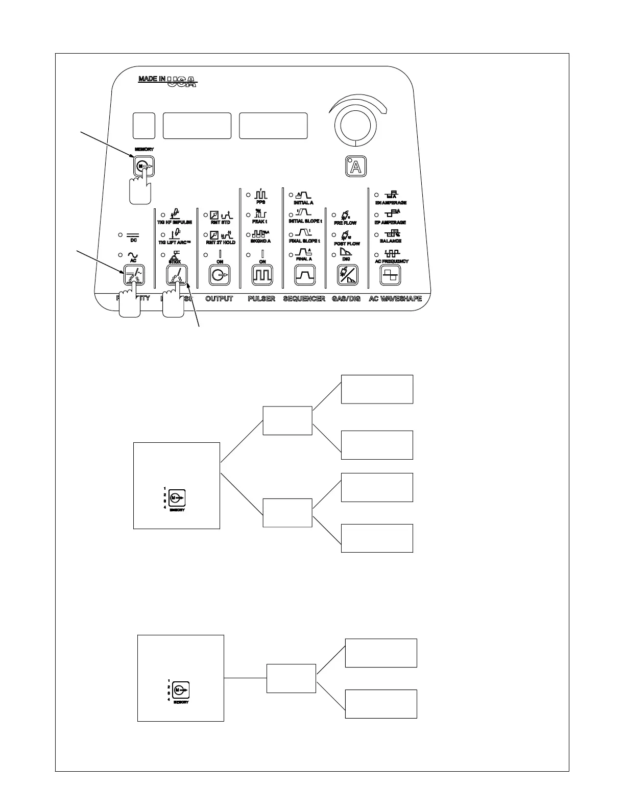
5-14. Memory (Program Storage Locations 1-9)
1 Memory (Program Storage
1-9) Switch Pad
2 Polarity Switch Pad (Dynasty
Only)
3 Process Switch Pad
To create, change, or recall a
welding parameters program,
proceed as follows:
First, press Memory switch pad until
the desired program storage loca-
tion (1-9) is displayed.
Second, press Polarity switch pad
until the desired polarity, AC or DC,
LED is illuminated
Third, press Process switch pad un-
til desired process, TIG HF Impulse,
TIG Lift Arc, or Stick, LED is illumi-
nated.
The program at the chosen location,
for the desired polarity and process,
is now the active program.
Fourth, change or set all desired pa-
rameters (see Section 5-15 for
parameters).
Memory Locations
1−9
AC
DC
TIG (HF or Lift)
TIG (HF or Lift)
Stick
Stick
For Dynasty Models, each memory location (1 thru 9) can store parameters
for both polarities (AC and DC), and each polarity can store parameters for
both process (TIG and Stick) for a total of 36 programs.
And
And
And
1
2
3
2nd
3rd
1st
Polarity And AC Waveshape Controls Are Available On Dynasty Models Only.
Memory Locations
1−9
DC
TIG (HF or Lift)
Stick
For Maxstar Models, each memory location (1 thru 9) can store parameters
for both process (TIG and Stick) for a total of 18 programs.
And
 Loading...