OM-216 869 Page 93
SECTION 14 − STICK WELDING (SMAW) GUIDELINES
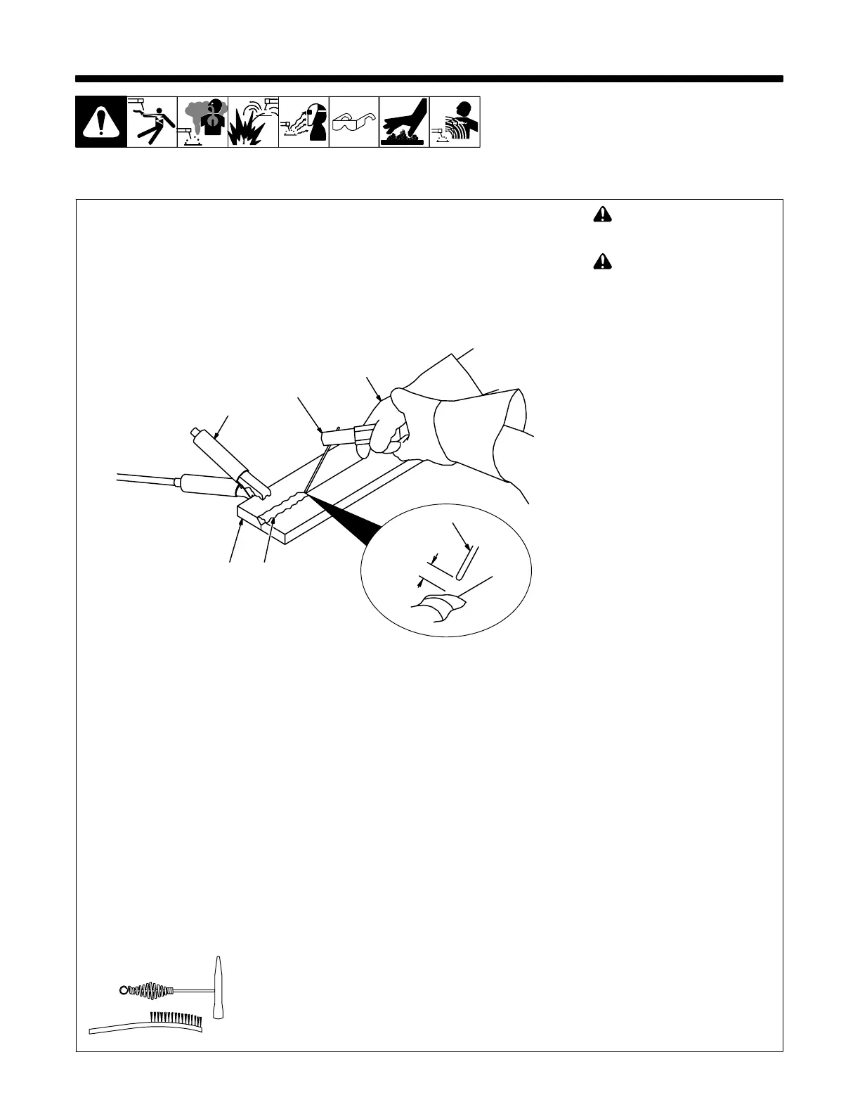
14-1. Stick Welding Procedure
stick 2007−04 − ST-151 593
! Weld current starts when
electrode touches work-
piece.
! Weld current can damage
electronic parts in vehicles.
Disconnect both battery
cables before welding on a
vehicle. Place work clamp as
close to the weld as possible.
1 Workpiece
Make sure workpiece is clean be-
fore welding.
2 Work Clamp
3 Electrode
A small diameter electrode requires
less current than a large one. Fol-
low electrode manufacturer’s
instructions when setting weld am-
perage (see Section 14-2).
4 Insulated Electrode Holder
5 Electrode Holder Position
6 Arc Length
Arc length is the distance from the
electrode to the workpiece. A short
arc with correct amperage will give
a sharp, crackling sound.
7 Slag
Use a chipping hammer and wire
brush to remove slag. Remove slag
and check weld bead before mak-
ing another weld pass.
Tools Needed:
1
4
3
5
2
7
6
 Loading...