OM-216 869 Page 36
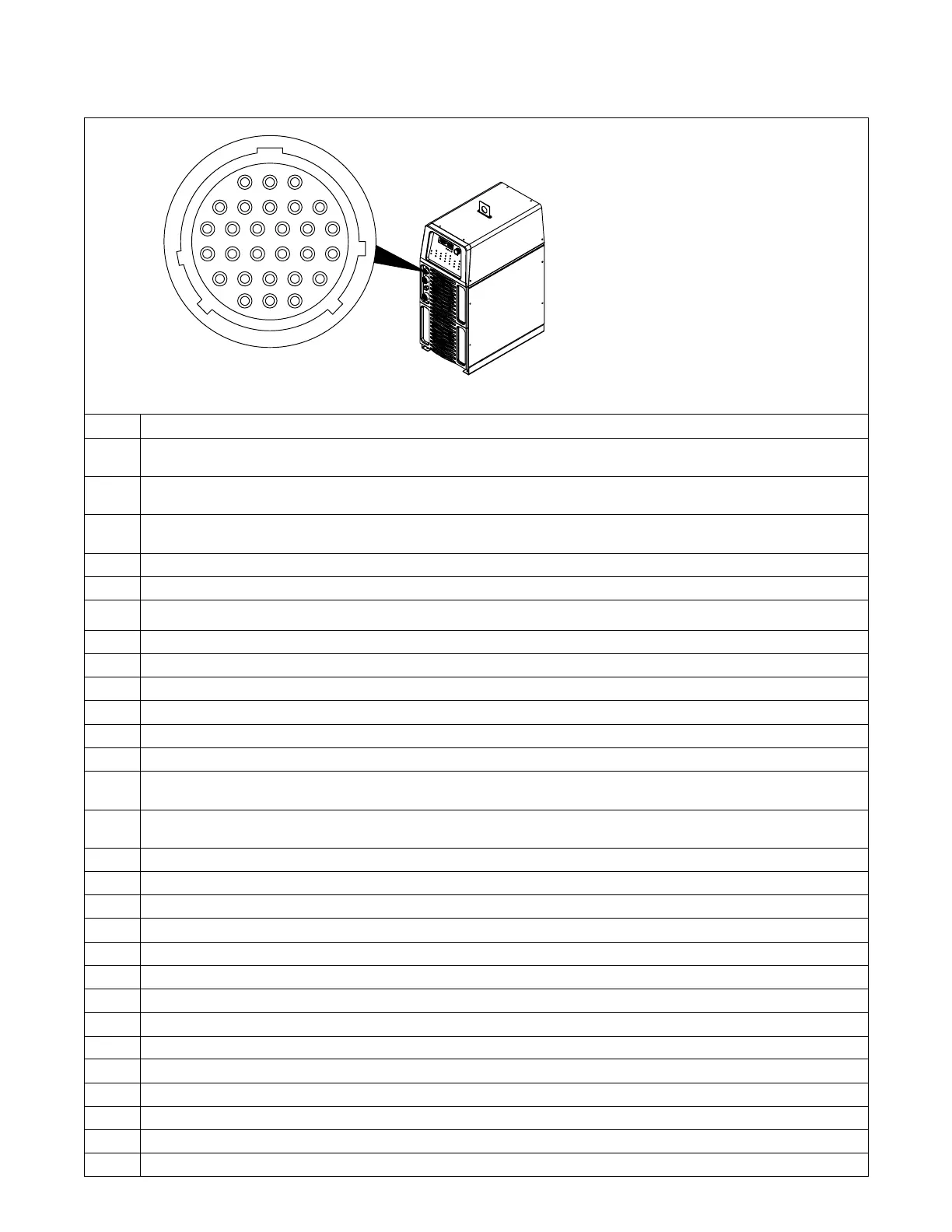
4-12. Automation Connection (For 28-Pin Receptacle If Present)
803 900-A / 218 716-A
1
4
9
15
21
26
28
25
20
14
8
3
2
76 5
13
12
11 10
19
18
17
16
24
23
22
27
Pin Pin Information For 28-Pin Receptacle RC28
1 Start/Stop - Closure to pin 8 starts the weld cycle. Opening closure stops weld cycle. During 2T operation, a momentary closure
(greater than 100 ms, but less than 3/4 seconds) starts and stops weld output.
2 Output enable - functional only in automation modes - Closure to pin 8 must be maintained at all times. If the closure between pins 2
and 8 is broken, an output disable occurs, Postflow begins to time out, and AUTO STOP will be displayed on the meters.
3 Gas - Closure to pin 8 turns on gas. This input will override Postflow, but if a Preflow time is entered, the Preflow cycle will time out
before arc initiation.
4 Valid arc, collector - Output is on when the contactor is on and there is less than 50 load volts (see Section 4-15).
5 Voltage feedback - +1 volt DC per 10 volts w/reference to pin 11.
6 Current feedback - +1 volt DC per 100 amperes w/reference to pin 11.
7 Not used
8 IGND isolation common
9 Valid arc, emitter - Output is on when the contactor is on and there is less than 50 load volts (see Section 4-15).
10 Memory Select 2 - See Section 4-13.
11 Remote control circuit common
12 Chassis common
13 Pulse lockout, collector - Output is on when in Initial Amperage, Initial Slope, Final Slope, Final Amperage, and Pulsed Background
time when the pulse frequency is less than 10 Hz (see Section 4-15).
14 Pulse lockout, emitter - Output is on when in Initial Amperage, Initial Slope, Final Slope, Final Amperage, and Pulse Background
time, when the pulse frequency is less than 10 Hz (see Section 4-15).
15 Memory select 0 - See Section 4-13.
16 Memory select 1 - See Section 4-13.
17 Command signal from remote control - 0 to +10 volts DC input.
18 +10 volts DC
19 HF disable - Disables high frequency when connected to pin 8.
20 Automation enable 1 - See Section 4-14.
21 Amperage EN common - See Section 4-14.
22 Amperage EN command - See Section 4-14.
23 Final slope, collector - Output is on when in Final Slope (see Section 4-15).
24 Final slope, emitter - Output is on when in Final Slope (see Section 4-15).
25 Automation enable 2 - See Section 4-14.
26 Amperage EP command (Dynasty models only) - See Section 4-14.
27 Amperage EP common (Dynasty models only) - See Section 4-14.
28 Polarity (Dynasty models only) - See Section 4-14.
 Loading...