EasyManuals Logo

Miller DYNASTY 700 User Manual

Miller DYNASTY 700
134 pages
To Next Page IconTo Next Page
To Previous Page IconTo Previous Page
Page #130 background imageLoading...
Page #130 background image
OM-216 869 Page 122
SECTION 17 PARTS LIST FOR COOLER
Hardware is common and
not available unless listed.
804 813-B
1
2
3
4
9
6
10
11
7
8
5
12
13
14
15
16
17
18
19
20
22
21
14
14
23
24
25
26
27
28
35
34
29
33
32
30
31
Figure 17-1. Main Assembly

Table of Contents

Questions and Answers:

Question and Answer IconNeed help?

Do you have a question about the Miller DYNASTY 700 and is the answer not in the manual?
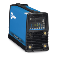
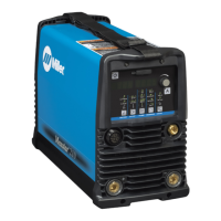
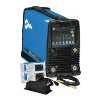
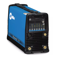
Miller DYNASTY 700 Specifications

General IconGeneral
Output Range5 - 700 A
Output Voltage Range10 - 40 V
Max Open Circuit Voltage80 V
ProcessesTIG, Stick
Duty Cycle60% at 700 A
Rated Output700 A at 60% Duty Cycle

Related product manuals