OM-206 360 Page 9
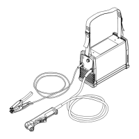
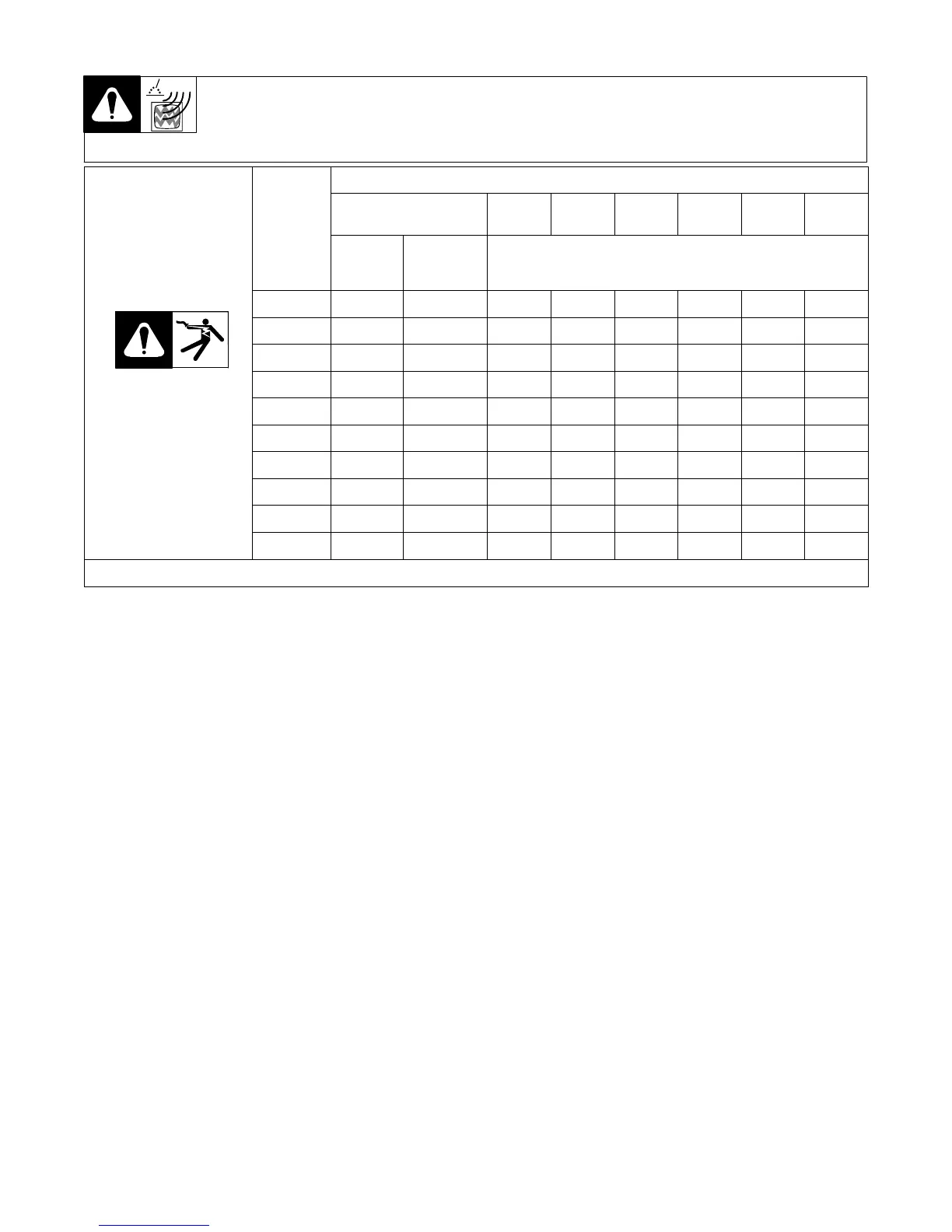
2-6. Weld Output Terminals And Selecting Cable Sizes
Y ARC WELDING can cause Electromagnetic Interference.
To reduce possible interference, keep weld cables as short as possible, close together, and down low, such as on the floor.
Locate welding operation 100 meters from any sensitive electronic equipment. Be sure this welding machine is installed
and grounded according to this manual. If interference still occurs, the user must take extra measures such as moving
the welding machine, using shielded cables, using line filters, or shielding the work area.
Total Cable (Copper) Length In Weld Circuit Not Exceeding
100 ft (30 m) Or Less
150 ft
(45 m)
200 ft
(60 m)
250 ft
(70 m)
300 ft
(90 m)
350 ft
(105 m)
400 ft
(120 m)
Welding
Amperes
10 − 60%
Duty
Cycle
60 − 100%
Duty Cycle
10 − 100% Duty Cycle
150 30 30 35 50 60 70 95 95
200 30 35 50 60 70 95 120 120
250 35 50 60 70 95 120 2 x 70 2 x 70
Turn Off power before
connectin
to weld out
ut
300 50 60 70 95 120 2 x 70 2 x 95 2 x 95
connecting to weld output
terminals.
350 60 70 95 120 2 x 70 2 x 95 2 x 95 2 x 120
400 60 70 95 120 2 x 70 2 x 95 2 x 120 2 x 120
500 70 95 120 2 x 70 2 x 95 2 x 120 3 x 95 3 x 95
600 95 120 2 x 70 2 x 95 2 x 120 3 x 95 3 x 120 3 x 95
700 120 2 x 70 2 x 95 2 x 120 3 x 95 3 x 120 3 x 120 4 x 120
800 120 2 x 70 2 x 95 2 x 120 3 x 120 3 x 120 4 x 120 4 x 120
Weld cable size = mm
2
S-0007-D