OM-206 360 Page 11
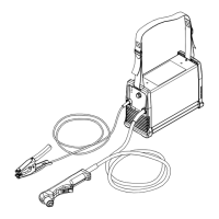
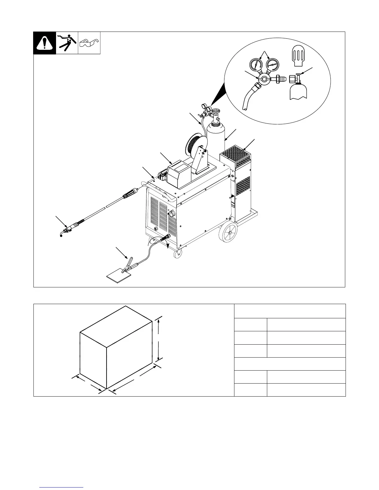
3-2. Typical MIG Connections
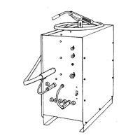
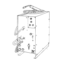
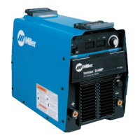
1 Power source
2 Work clamp (connect to re-
ceptacle as shown)
3 Water cooler for torch
4 Cylinder (chain to running
gear)
5 Cylinder valve
Open valve slightly so gas flow
blows dirt from valve. Close valve.
6 Regulator/Flow gauge
Install so face is vertical
7 Flow adjust
8 Gas supply line
9 Wire feeder
10 MIG torch
1
5
6
7
3
4
8
9
2
10
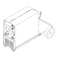
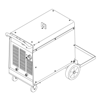
3-3. Dimensions And Weights
mens
ons
A 1040 mm
C
B 435 mm
C 760 mm
Weight
A
35 146 kg
B
45 175 kg