OM-264259 Page 10
SECTION 3 − DEFINITIONS
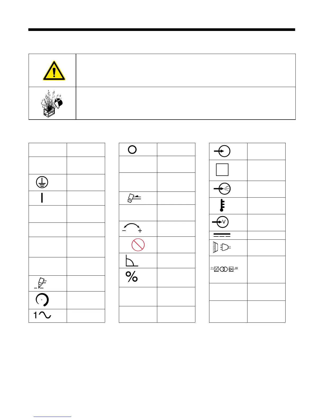
3-1. Additional Safety Symbols And Definitions
. Some symbols are found only on CE products.
Warning! Watch Out! There are possible hazards as shown by the symbols.
Safe1 2012−05
When power is applied failed parts can explode or cause other parts to explode.
Safe26 2012−05
3-2. Miscellaneous Symbols And Definitions
. Some symbols are found only on CE products.
A
Amperes
V
Volts
Protective Earth
(Ground)
On
U
0
Rated No Load
Voltage (OCV)
I
1max
Rated Maximum
Supply Current
IP
Degree Of
Protection
I
1eff
Maximum Effec-
tive Supply Cur-
rent
Plasma Arc
Cutting (PAC)
Increase
Single Phase
Off
U
1
Primary Voltage
I
2
Rated Welding
Current
Loose Shield Cup
pf
power factor
Adjust Air/Gas
Pressure
No − Do Not Do
This
Constant Current
Percent
U
2
Conventional
Load Voltage
X
Duty Cycle
Input
S
Suitable for Some
Hazardous
Locations
Low Air Pressure
Light
Temperature
Voltage Input
(Power)
Direct Current
Line Connection
Single Phase
Static Frequency
Converter-
Transformer-
Rectifier
Hz
Hertz
S
1
Power Rating,
Product Of
Voltage And
Current (KVA)
 Loading...