. A complete Parts List is available at www.MillerWelds.com
OM-264259 Page 15
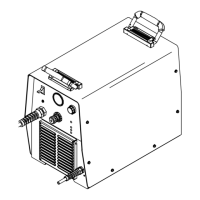
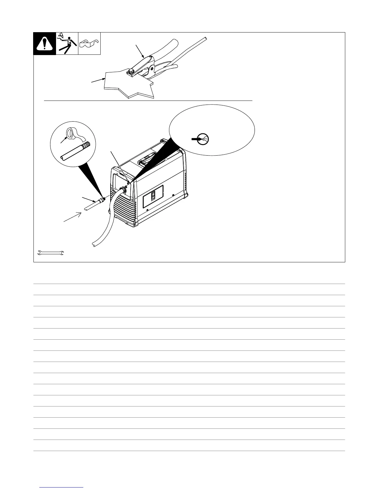
5-2. Connecting Work Clamp and Gas/Air Supply
1 Work Clamp
2 Workpiece
. Connect work clamp to portion
of workpiece that does not fall
away after being cut.
Connect work clamp to a clean,
paint-free location on workpiece, as
close to cutting area as possible.
. Use only clean, dry air with 90
to 120 psi (621 to 827 kPa)
pressure @ 6.75 SCFM
(191L/min) minimum.
. Use filter kit 300491 or 228926
where conditions at the work
site allow moisture, oil or other
particulates into the air line.
3 Gas/Air Filter Inlet Opening
4 Hose
. Hose must have a minimum
inside diameter of 3/8 in.
(9.5 mm).
5 Teflon Tape
Obtain hose with 1/4 NPT right-
hand thread fitting. Wrap threads
with teflon tape (optional) or apply
pipe sealant, and install fitting in
opening. Route hose to gas/air
supply.
NOTICE − Exceeding input
pressure rating of 120 PSI (827
kPa) can damage unit.
Tools Needed:
9/16 in.
3
4
Ref. 803 640-A / Ref. 237017 / Ref. 805 160-A
Rear of Unit
5
1
2
From
Gas/Air
Supply
90–120PSI
(621–827kPa)
AIR/N
2
Notes
 Loading...