 Loading...
Do you have a question about the Miller Spectrum 875 and is the answer not in the manual?
| Amperage Output | 20-60 A |
|---|---|
| CNC Interface | Optional |
| Gas Supply | Clean, dry, oil-free air or nitrogen |
| Input Frequency | 50/60 Hz |
| Output Current Range | 20-60 A |
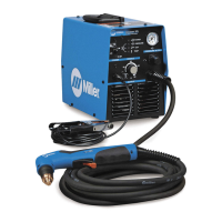
| Welding Process | Plasma cutting |
| TIG Start | Not applicable |
| Rated Output | 60 A |
| Cutting Capability | 3/4 in (19 mm) |
| Cutting Capacity | 1 in (25 mm) |
| Severance Capacity | 1-1/4 in (32 mm) |
| Input Phase | 1- or 3-Phase |
| Duty Cycle | 60% |