. A complete Parts List is available at www.MillerWelds.com
OM-264259 Page 22
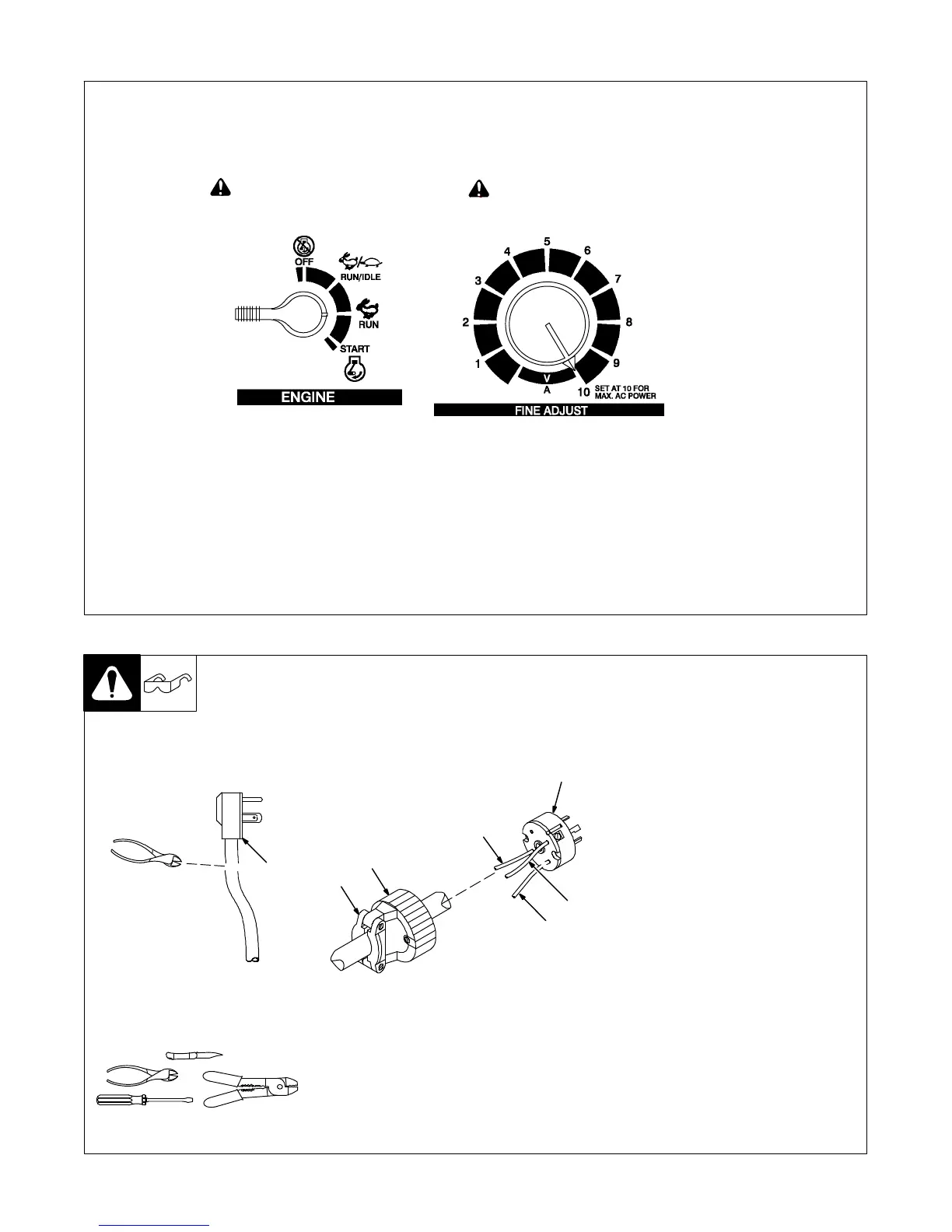
5-10. Generator Settings For Plasma Cutter Operation
Ref. 803 222
! Engine Control Switch must be set at
“RUN” position − not “RUN/IDLE”.
! Set generator Fine Adjustment Control to 10
for maximum auxiliary power, if applicable.
. The peak KW at arc stretch of this plasma power source
is 15.5 KW. Reducing output to 45 amps may be necessary
to operate the unit using a 10 KW generator.
5-11. Installing Alternative Plug
1 Supplied 230 VAC Plug
Cut cord close to plug.
2 Alternative Plug (230 VAC
Plug Shown)
3 Input (Black Lead)
(Brass) Terminal
4 Input (White Lead)
(Brass) Terminal
5 Ground (Green) Terminal
6 Outer Shell
7 Cord Grip
Strip cord jacket back enough to
separate conductors.
Strip conductors enough to make
good contact with plug terminals.
Make plug connections and reinstall
outer shell and cord grip. Tighten
assembly screws onto shell. Do not
overtighten.
Ref. 801 305-A / 801 611
. This procedure is necessary if the unit is to be connected
to a 208/230 VAC receptacle that requires a plug that is
different from the supplied plug.
Tools Needed:
1
6
7
2
3
4
5
 Loading...