. A complete Parts List is available at www.MillerWelds.com
OM-264259 Page 17
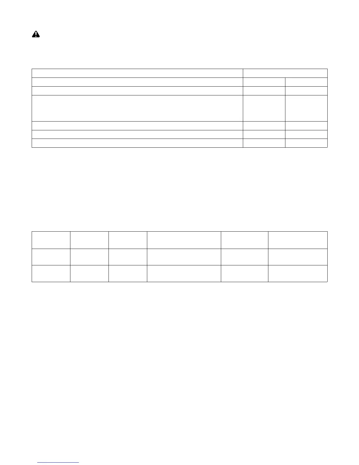
5-5. Electrical Service Guide
Elec Serv 2017−01
Failure to follow these electrical service guide recommendations could create an electric shock or fire hazard. These recommenda-
tions are for a dedicated circuit sized for the rated output and duty cycle of the welding power source.
In dedicated circuit installations, the National Electrical Code (NEC) allows the receptacle or conductor rating to be less than the rating
of the circuit protection device. All components of the circuit must be physically compatible. See NEC articles 210.21, 630.11, and
630.12.
50/60 Hz 1-Phase
Input Voltage (V) 208 230
Input Amperes (A) At Rated Output 47 42
Max Recommended Standard Fuse Rating In Amperes
1
Time-Delay Fuses
2
50 50
Normal Operating Fuses
3
70 60
Min Input Conductor Size In AWG (mm
2
)
4
10 (6) 10 (6)
Max Recommended Input Conductor Length In Feet (Meters) 55 (17) 67 (21)
Min Grounding Conductor Size In AWG (mm
2
)
4
10 (6) 10 (6)
Reference: 2017 National Electrical Code (NEC) (including article 630)
1 If a circuit breaker is used in place of a fuse, choose a circuit breaker with time-current curves comparable to the recommended fuse.
2 “Time-Delay” fuses are UL class “RK5” . See UL 248.
3 “Normal Operating” (general purpose - no intentional delay) fuses are UL class “K5” (up to and including 60 amps), and UL class “H” ( 65 amps and
above).
4 Conductor data in this section specifies conductor size (excluding flexible cord or cable) between the panelboard and the equipment per NEC Table
310.15(B)(16) and is based on allowable ampacities of insulated copper conductors having a temperature rating of 167°F (75°C) with not more than
three single current-carrying conductors in a raceway. If a flexible cord or cable is used, minimum conductor size may increase. See NEC Table
400.5(A) for flexible cord and cable requirements.
5-6. Extension Cord Data
. When calculating max. cord length, remember to include conductor length from line disconnect device to input power receptacle.
Input Voltage
Input Power
Phase
Hertz
Fuse Size Or
Circuit Breaker Rating
Conductor Size Max. Cord Length
208 V 1 50/60
Time-Delay
2
50 A
Normal Operating
3
70 A
10 AWG 55 ft (17 m)
230 V 1 50/60
Time-Delay
2
50 A
Normal Operating
3
60 A
10 AWG 67 ft (21 m)
2 “Time-Delay” fuses are UL class “RK5” .
3 “Normal Operating” (general purpose − no intentional delay) fuses are UL class “K5” (up to and including 60 amp), and UL class “H” ( 65 amp and
above).
 Loading...