. A complete Parts List is available at www.MillerWelds.com
OM-264259 Page 23
SECTION 6 − OPERATION
EGUOGTUC
V
V
REWOP
ERUSSERP
PUC
PMET
NO
FFO
A
04
05
03
02
06
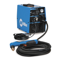
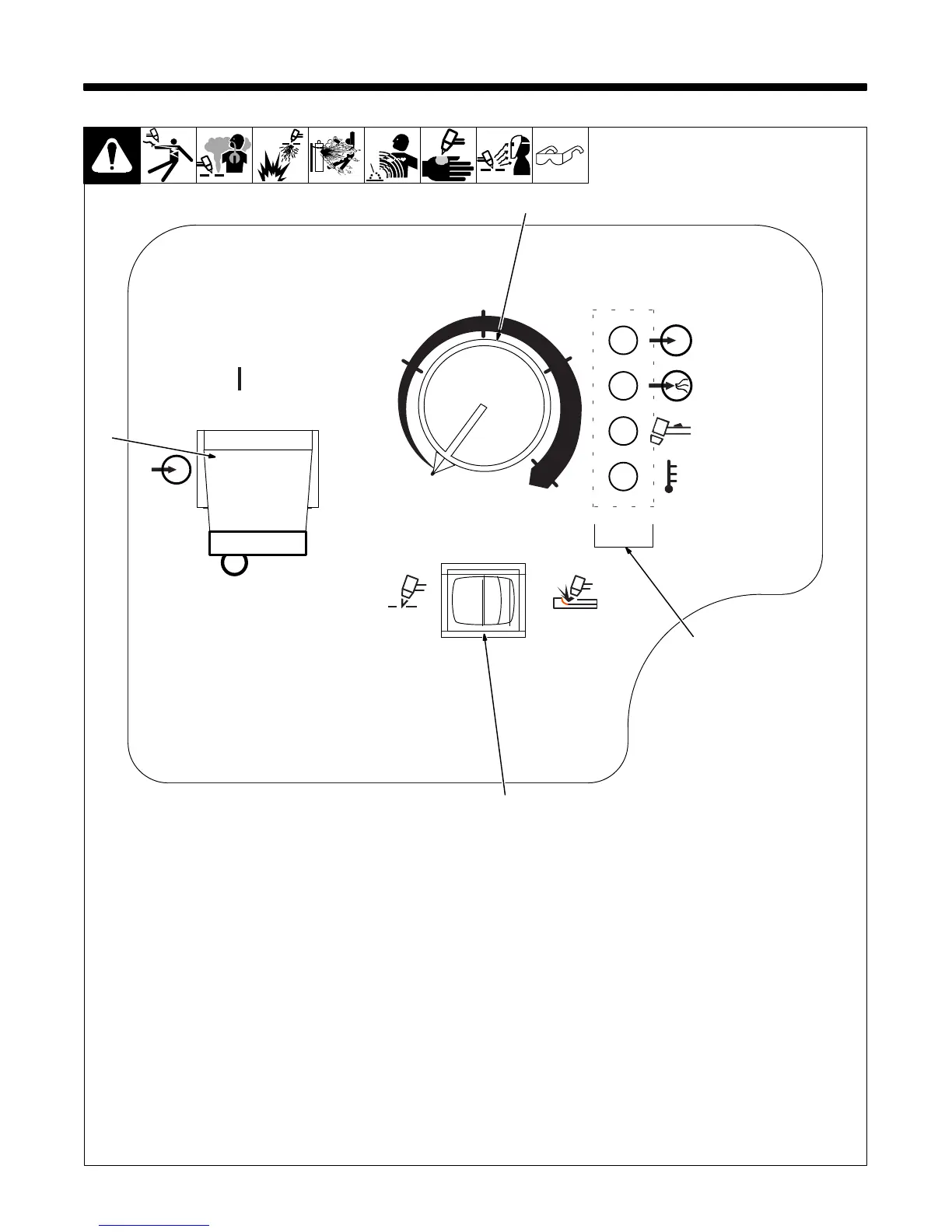
1 Output Control
Use control to set cutting output.
2 Status Lights (See Section 8-6)
3 Power Switch
. The fan will operate for approximately 10
seconds after power switch is placed in
the Off position to reduce DC bus
voltage.
4 Cut/Gouge Switch
Place switch in appropriate position for de-
sired process. Unit will automatically regu-
late pressure to 75 psi (517 kPa) for cutting
and 60 psi (413 kPa) for gouging. Pilot cur-
rent is automatically increased in gouge
mode to provide better gouging starts.
. Use only clean, dry air with 90 to 120 psi
(621 to 827 kPa) pressure. Prevent
moisture from entering air supply at
extreme cold temperatures.
. Use filter kit 300491 or 228926 where
conditions at the work site allow mois-
ture, oil or other particulates into the air
line.
Ref. 234 155-A
2
4
3
1
6-1. Controls
 Loading...