. A complete Parts List is available at www.MillerWelds.com
OM-265 363 Page 24
SECTION 5 − SYSTEM CONNECTIONS
5-1. Terminal Strip TE2 and Remote Receptacle RC1 Information
Function Socket On RC1 Terminal On TE2 Contact Information
Electrical Input Power A, B − 24 VAC. Protected by circuit breaker CB2.
C, D − 24 VAC common.
Accessory Serial Communication
J − +Accessory RS−485 communication.
V − −Accessory RS−485 communication.
Q − Accessory serial communication common.
Shield H − Contact E/F shield drain lead.
Power Source Serial
Communication
P − +Power source RS−485 communication.
N − −Power source RS−485 communication.
Z − Power source serial communication common.
Shield G − Contact H/J shield drain lead.
PS/PS Communication K − Communication link in.
Power Source Synchronization E − Synchronization in.
Volt Sense W − + Volt sense.
X − Reserved for − volt sense.
Shield N − Contact M/L shield drain lead.
Remote Voltage Sensing
− N Voltage sensing signal from Work weld output terminal.
− P Voltage sensing signal from Electrode weld output terminal.
− TP
Test point.
− Not Applicable
2
1
4
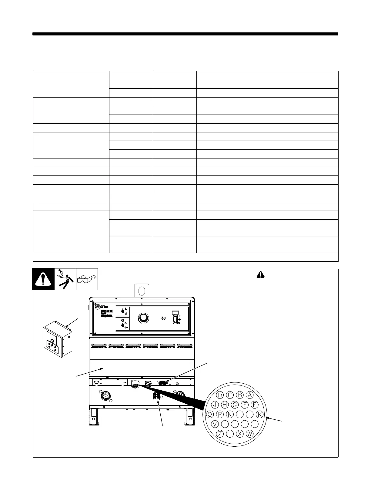
! Turn Off welding power
source before opening ac-
cess door.
1 Access Door
2 Remote Receptacle RC1
(Mounted Inside Access Area)
3 Terminal Strip TE2
4 SubArc Interface
Connect RC1 on SubArc interface
to Remote receptacle RC1 on pow-
er source.
5 Modbus RTU
For use with optional PLC control.
. DC 650/800 model shown. Lo-
cation is the same for DC
1000/1250 models.
3
Ref. 265 207-A / 265 690-B
5