. A complete Parts List is available at www.MillerWelds.com
OM-265 363 Page 34
SECTION 8 − PLC OPERATION
8-1. Automation Interface Hardware Configuration (PLC Users Only)
Ref. 265 207-A
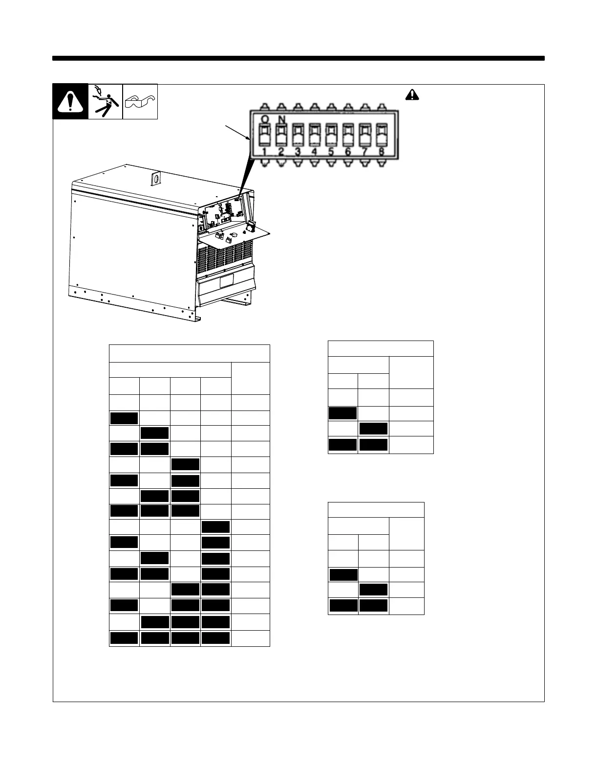
! Disconnect and lockout/tag-
out input power before con-
necting input conductors from
unit. Follow established pro-
cedures regarding the install-
ation and removal of lockout/
tagout devices.
1 Switch DIP 1
Configure switch DIP 1 on Automa-
tion Interface board PC4 to match the
network baud rate and parity set-
tings, and set the MODBUS address
for this device. (see Table 8-1 thru
Table 8-3).
1
DIP1
DIP1
Rate
12 3 4
Address
56
ON ON ON ON 40
ON ON 9600
ON ON ON 41
ON 19200
ON ON ON 42
ON 38400
ON ON 43
reserved
ON ON ON 44
ON ON 45
DIP1
Parity
ON ON 46
78
ON 47
ON ON EVEN
ON ON ON 60
ON ODD
ON ON 61
ON NONE
ON ON 62
reserved
ON 63
ON ON 64
ON 65
ON 66
67
Table 8-1. MODBUS Address
OFF
OFF
OFF
OFF
OFF
OFF
OFF
OFF
OFF
OFF
OFF
OFF
OFF OFF
OFF
OFF
OFF OFF
OFF OFF OFF
OFF
OFF
OFF
OFF
OFF
OFF
OFF
OFF
OFF
OFF OFF
OFF
OFF OFF
OFF OFF
OFF OFF OFF
Table 8-2. Baud Rate Data
Table 8-3. Parity Data
 Loading...