. A complete Parts List is available at www.MillerWelds.com
OM-265 363 Page 33
SECTION 7 − POWER SOURCE OPERATION
7-1. Controls
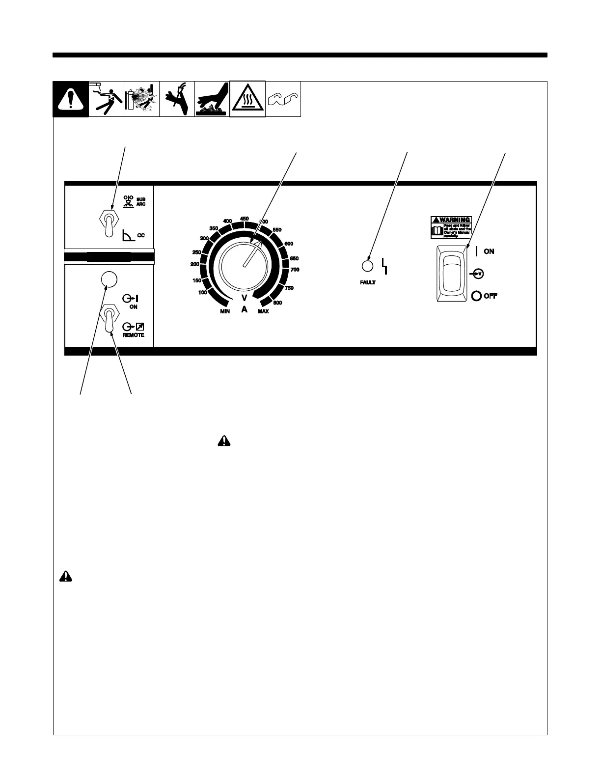
1 Process Selector Switch
Place switch in position for desired process.
• Sub Arc Mode − For SAW (Sub Arc) appli-
cations.
• CC Mode - For gouging applications.
2 Output Control Switch (Contactor)
For weld output, place switch in On position.
Switch is disabled when a SubArc Interface
is connected to Remote Receptacle RC1
and powered on, or when a PLC has active
control through the Modbus RTU connector.
It is disabled if the power source is a follow-
ing unit in parallel configuration.
3 Output On LED
! Output is on and weld output studs
are energized when LED is lit.
! Turn Off power before connecting re-
mote device.
For front panel control of output, place switch
in On position. For remote control of output,
place switch in Remote position, and con-
nect remote device to RC1. Remote control
provides full range of unit output regardless
of A/V Adjust control setting. If the output is
on before a remote accessory is powered
on, the power source will ignore the acces-
sory until the output is turned off.
4 Amperage/Voltage Adjustment Control
When Process Selector switch is in the
Constant Current position, turn control
clockwise to increase amperage. Read am-
perage from outer scale of control. Numbers
on scale are for reference only.
When the Process Selector switch is in the
SubArc position, Control can be adjusted
while welding.
5 Status/Trouble Light
When a fault occurs, LED flashes a se-
quence code to identify the fault (see section
9-1).
6 Power Switch With Indicator Light
262 962-B
1
4
2
3
5
6
PROCESS
OUTPUT
A/V ADJUST


 To Next Page