OM-253893 Page 13
SECTION 5 − CONNECTIONS
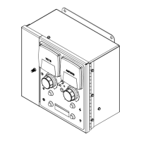
5-1. Left Side Panel Connections
263203-A
1
2
1 Receptacle
2 Keyway
3 Access Holes - For Customer
Use: Connections To Terminal
Strips.
! Turn Off welding power
source and weld control and
disconnect input power be-
fore opening access door.
Install strain relief (customer
supplied) in access hole.
Route incoming cables through
user access hole prior to making
connections to internal terminal
blocks.
4 Receptacle RC3:
Connection To Flux Hopper.
5 Receptacle RC1: Connection
To Welding Power Source.
6 Receptacle RC2: Connection
to Wire Drive Motor
To connect matching interconnect-
ing cord to one of the above
receptacles, align keyway, insert
plug, and tighten twist lock collar.
Connect remaining end of cord to
matching receptacle on applicable
equipment.
3
Bottom
4
5
6
Left Panel
5-2. Receptacle RC2 Information
Socket Socket Information
Wire Drive Hookups
J Positive (+) motor armature (38 VDC motor).
A Negative (−) motor armature (38 VDC motor).
H Motor identification (resistor across H and B).
C Shield drain leads.
I Encoder VCC (+5 VDC).
K Encoder channel A.
B Encoder common and motor identification (resistor across H and B).
E Reserved for negative volt sense lead
F Positive volt sense lead