OM-253893 Page 20
JOG
SPEED
0−10SEC.
t1
PREFLOW
TIME
RUNIN
SPEED
CRATER/
BURNBACK
OUTPUT
CRATER
SPEED
0−5SEC.
t
CRATER
TIME
0−5SEC.
BURNBACK
TIME
0−10SEC.
t2
POSTFLOW
TIME
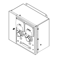
-2. Inside Panel Controls
1 Jog Speed
This control sets the speed at which
welding wire is advanced out of the weld-
ing torch (Inch Down) or retracted into the
torch (Inch Up). When set to minimum,
the jog speed is controlled by the front
panel Wire Speed control.
2 Preflux Time
This control sets the length of time, 0 to 10
seconds, during which flux will flow be-
fore the arc starts. During this time, only
the flux valve is active. Note: Flux valve
remains active throughout the weld
cycle.
3 Run-In Speed Control
This control sets the wire feed speed be-
tween the time the weld cycle begins and
before an arc is established. After arc ini-
tiation, the wire feed speed is set by the
front panel Wire Speed control.
4 Crater/Burnback Output Control
Use this control to set the output level of
the power source while the weld cycle is
in the crater fill and burnback modes.
5 Crater Speed Control
Use this control to set the wire feed speed
while the weld cycle is in the crater fill
mode.
6 Crater Time Control
This 0 to 5 seconds adjustable control
sets the length of time the weld cycle
stays in the crater fill mode. While in this
mode, the power source output is set by
the Crater/Burnback Output control rath-
er than the front panel Output control.
Also, the wire feed speed is set by the
Crater Speed control rather than the front
panel Wire Speed control.
7 Burnback Time Control
This 0 to 5 seconds adjustable control al-
lows setting of the time the welding wire
remains electrically energized after the
drive motor stops. The burnback timer
starts after the crater timer times out. By
adjusting the control properly, the wire
neither freezes in the weld puddle nor in
the contact tube of the torch. If the wire
freezes in the puddle, increase the burn-
back time. If the wire freezes in the torch,
decrease the burnback time.
8 Postflow Time Control
This 0 to 5 seconds adjustable control al-
lows setting of the time the flux valve re-
mains activated after the Stop button is
pressed. For Submerged Arc Welding,
this control is usually set to zero mini-
mum.
9 CC/CV Switch
Set this switch to tell the system interface
analog you want to use constant current
(CC) or constant voltage (CV). This
switch overrides the switch on the power
source.
10 Motor Direction Switch
Set this switch to tell the System Interface
Analog the desired motor direction.
Ref. 803023-B / 236567-A / 264023-A
1
2
3
4
5
6
7
8
9
10
MOTOR
CC
CV