Parameter Menus Operations
2 - 20 0070-10-0666-01 Trio™ Operating Instructions
Modified Chest Lead (MCL) Monitoring
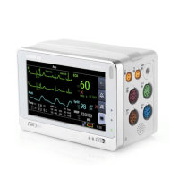
FIGURE 2-22 MCL Monitoring with a
3-wire Lead Set (AHA)
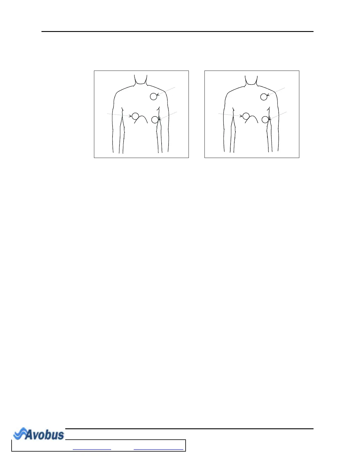
FIGURE 2-23 MCL Monitoring with a
3-wire Lead Set (IEC)
• Place the RA (white) electrode under the
patient’s left clavicle, at the mid-
clavicular line within the rib cage frame.
• Place the LA (black) electrode on the
right sternal border, at the fourth
intercostal space within the rib cage
frame.
• Place the LL (red) electrode on the
patient’s lower left abdomen within the
rib cage frame.
Select ECG Lead I for MCL
1
monitoring.
Lead I is the direct electrical line between
the RA (white) electrode and the LA (black)
electrode.
Select ECG Lead II for MCL
6
monitoring.
Lead II is the direct electrical line between
the RA (white) electrode and the LL (red)
electrode.
• Place the R (red) electrode under the
patient’s left clavicle, at the mid-
clavicular line within the rib cage frame.
• Place the L (yellow) electrode on the
right sternal border, at the fourth
intercostal space within the rib cage
frame.
• Place the F (green) electrode on the
patient’s lower left abdomen within the
rib cage frame.
Select ECG Lead I for MCL
1
monitoring.
Lead I is the direct electrical line between
the R (red) electrode and the L (yellow)
electrode.
Select ECG Lead II for MCL
6
monitoring.
Lead II is the direct electrical line between
the L (red) electrode and the F (green)
electrode.
To Purchase, Visit Avobus.com or call 1-800-674-3655

 Loading...