2
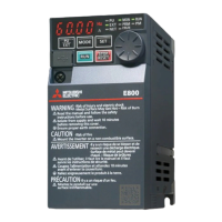
Product checking and parts identification
1.1 Product checking and parts identification
T$8#,%&0"5&.$45+05+&#$9&,"5,%&0"5&,#8#,.0'&87#05&($&0"5&*+($0&,(45+&#$9&0"5&+#0.$/&87#05&($&0"5&.$45+05+&-.95&*#,5&0(
5$-)+5&0"#0&0"5&8+(9),0&#/+55-&C.0"&'()+&(+95+&#$9&0"5&.$45+05+&.-&.$0#,06
Operation panel (FR-DU07)
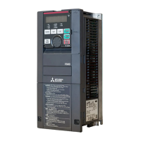
Front cover
EMC filter ON/OFF connector
Control circuit
terminal block
AU/PTC switchover switch
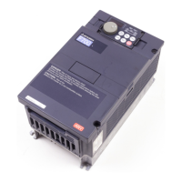
Main circuit terminal block
Charge lamp
Lit when power is
supplied to the main
circuit
Power lamp
Lit when the control circuit
(R1/L11, S1/L21) is supplied
with power.
Cooling fan
PU connector
RS-485 terminals
Connector for plug-in option connection
(Refer to the instruction manual of options.)
Alarm lamp
Lit when the inverter is
in the alarm status
(fault).
Capacity plate
Inverter model
Serial number
Capacity plate
Rating plate
Voltage/current input switch
- EC
FR-F740-00126-EC
00126
Symbol
00023
to
12120
Displays the rated current
Type Number
FR --F740
Symbol
F740
Voltage Class
Three-phase
400V class
Rating plate
Inverter model
Input rating
Output rating
Serial number
FR-F740-00126-EC
LD (50 C) XXA
SLD (40 C) XXA
Surrounding Air
Temperature
LD 120% 60s, 150% 3s 50 C
SLD 110% 60s, 120% 3s 40 C
• Inverter Model
Combed shaped
wiring cover
Overload Current Rating
(Refer to page 30)
(Refer to page 98)
(Refer to page 5)
(Refer to page 13)
(Refer to page 14)
(Refer to page 5)
x :''&==-)8
^3<1#'-0&)#@*]*1L#=')&Y=#JXXN2X#-)#%&==K
(Refer to installation guideline)
O-;&% +')&Y#+*_&#JBBK E7BA&)
>>>G_B&&>>F]E 1_&u_^ F
>>F=>&0(&>>_G> 1`&u`> ]
>>`=>B&>>E]> 1`&u^> F
^RG#)&<'(-)#=7??%*&;#JX!\XX#-)#B-)&K
^$8&A-%(#@-)#,<1L*1L#(,&#*10&)(&)#JXXQQX#(-#XN\4XK#
O-;&% $8&A-%(#=*_& E7BA&)
>>==> 1G ]
>>H_>&0(&>_EF> 1F> ]
>`_]>&0(&>EG_> 1F] ]
(Refer to page 29)
(Refer to page 22)
(Refer to page 16)
(Refer to page 12, 155)
(Refer to page 294)
(Refer to page 14)
 Loading...