17
1. INTRODUCTION
1.1 Product checking and accessories
1
2
3
4
5
6
7
8
9
10
1.1 Product checking and accessories
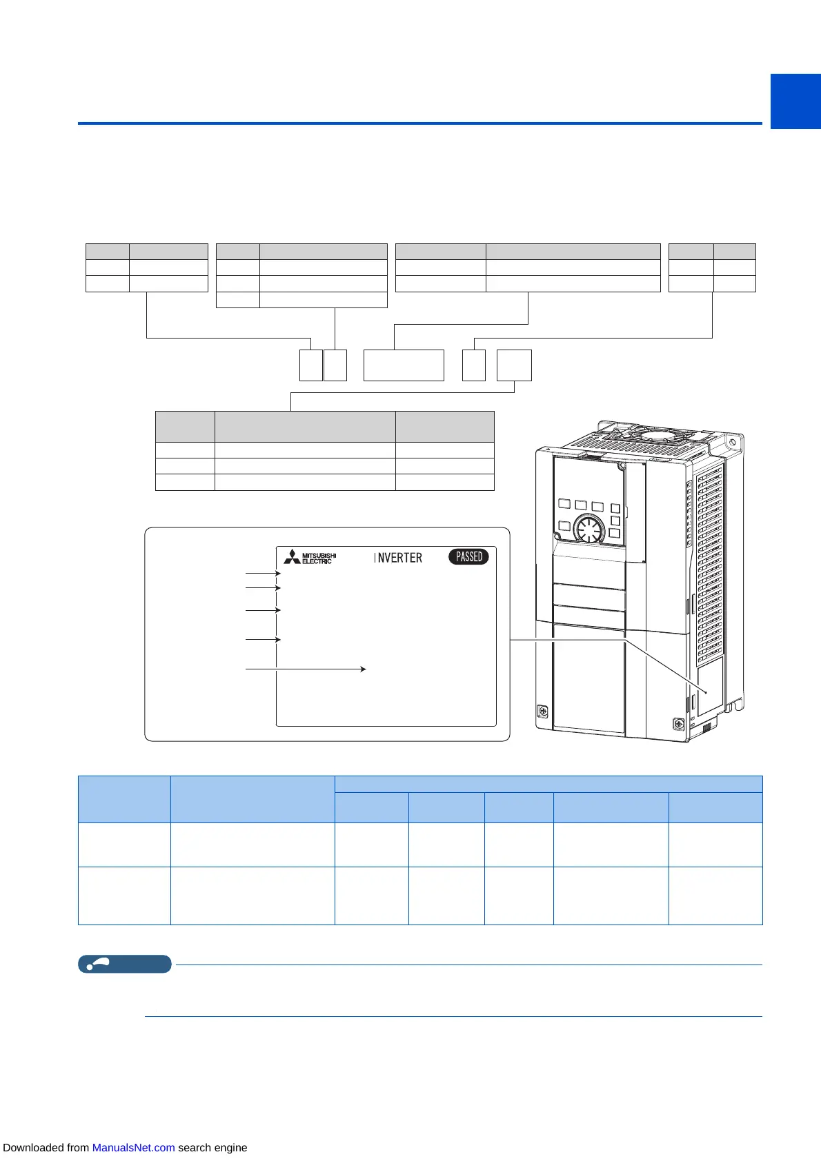
Unpack the product and check the rating plate and the capacity plate of the inverter to ensure that the model agrees with the
order and the product is intact.
Inverter model
*1 Specification differs by the type. Major differences are shown in the following table.
*2 Applicable for the FR-F820-00340(7.5K) or higher, and the FR-F840-00170(7.5K) or higher.
NOTE
• In this Instruction Manual, the inverter model name consists of the inverter rated current and the applicable motor capacity.
Example) FR-F820-00046(0.75K)
Rating plate
Input rating
Output rating
SERIAL
Inverter model
,1387;;;;;
02'(/)5)
287387;;;;;
6(5,$/;;;;;;;;;
0$'(,1;;;;;
Country of origin
F R - F 8 2 0 -
00046
- 1
400V class
Symbol Voltage class
200V class
4
2
CA
Symbol Type
*1
FM
-2
-1
Symbol Description
0.75K to 560K
00023 to 12120
LD rated inverter capacity (kW)
SLD rated inverter current (A)
Symbol Structure, functionality
Standard model0
Separated converter type
2
IP55 compatible model6
Symbol
Circuit board coating
(conforming to IEC60721-3-3: 1994 3C2/3S2)
WithoutNone
With
With
Plated conductor
Without
With
Without
-06
*2
-60
Type Monitor output
Initial setting
Built-in EMC
filter
Control logic
Rated
frequency
Pr.19 Base
frequency voltage
Pr.570 Multiple
rating setting
FM (terminal FM
equipped model)
Terminal FM (pulse train output)
Terminal AM (analog voltage
output (0 to ±10 VDC))
OFF Sink logic 60 Hz
9999 (same as the
power supply voltage)
1 (LD rating)
CA (terminal CA
equipped model)
Terminal CA (analog current
output (0 to 20 mADC))
Terminal AM (analog voltage
output (0 to ±10 VDC))
ON Source logic 50 Hz
8888 (95% of the
power supply voltage)
0 (SLD rating)
Downloaded from ManualsNet.com search engine

 Loading...