345
5. PARAMETERS
5.8 (M) Item and output signal for monitoring
1
2
3
4
5
6
7
8
9
10
• When Pr.655 = "1 or 11" (remote output data retained at power OFF), take measures to keep the control circuit power ON,
such as connecting terminal R1/L11 with terminal P/+ and connecting terminal S1/L21 with terminal N/- (while power is
supplied via input terminals R/L1, S/L2 and T/L3). If the control power is not retained, the output signal after the inverter power
turns ON is not guaranteed to work. When connecting the high power factor converter FR-HC2, assign the instantaneous
power failure detection (X11) signal to an input terminal to input the IPF signal from the FR-HC2 to the terminal for X11 signal.
Pr.54 FM/CA terminal function selectionpage 314
Pr.158 AM terminal function selectionpage 314
Pr.290 Monitor negative output selectionpage 314
Pr.291 Pulse train I/O selectionpage 314
5.8.12 Fault code output selection
When a fault occurs, the corresponding data can be output as a 4-bit digital signal using via an open collector output terminal.
The fault code can be read using an input module of programmable controller, etc.
• Fault codes can be output to the output terminals by setting Pr.76 Fault code output selection = "1 or 2".
• When the setting is "2", a fault code is only output when a fault occurs. In normal operation the terminal outputs the signal
assigned in Pr.191 to Pr.194 (output terminal function selection).
• The fault codes that can be output are shown in the following table. (0: Output transistor OFF, 1: Output transistor ON)
*1 When Pr.76 = "2", the terminal outputs the signal assigned by Pr.191 to Pr.194.
NOTE
• If an error occurs while Pr.76 ≠ "0", the output terminals SU, IPF, OL, and FU output the signals in the table above regardless
of the settings in Pr.191 to Pr.194 (Output terminal function selection). Take caution when controlling the inverter with the
output signals set by Pr.191 to Pr.194.
Parametersreferredto
Pr.190 to Pr.196 (Output terminal function selection)page 330
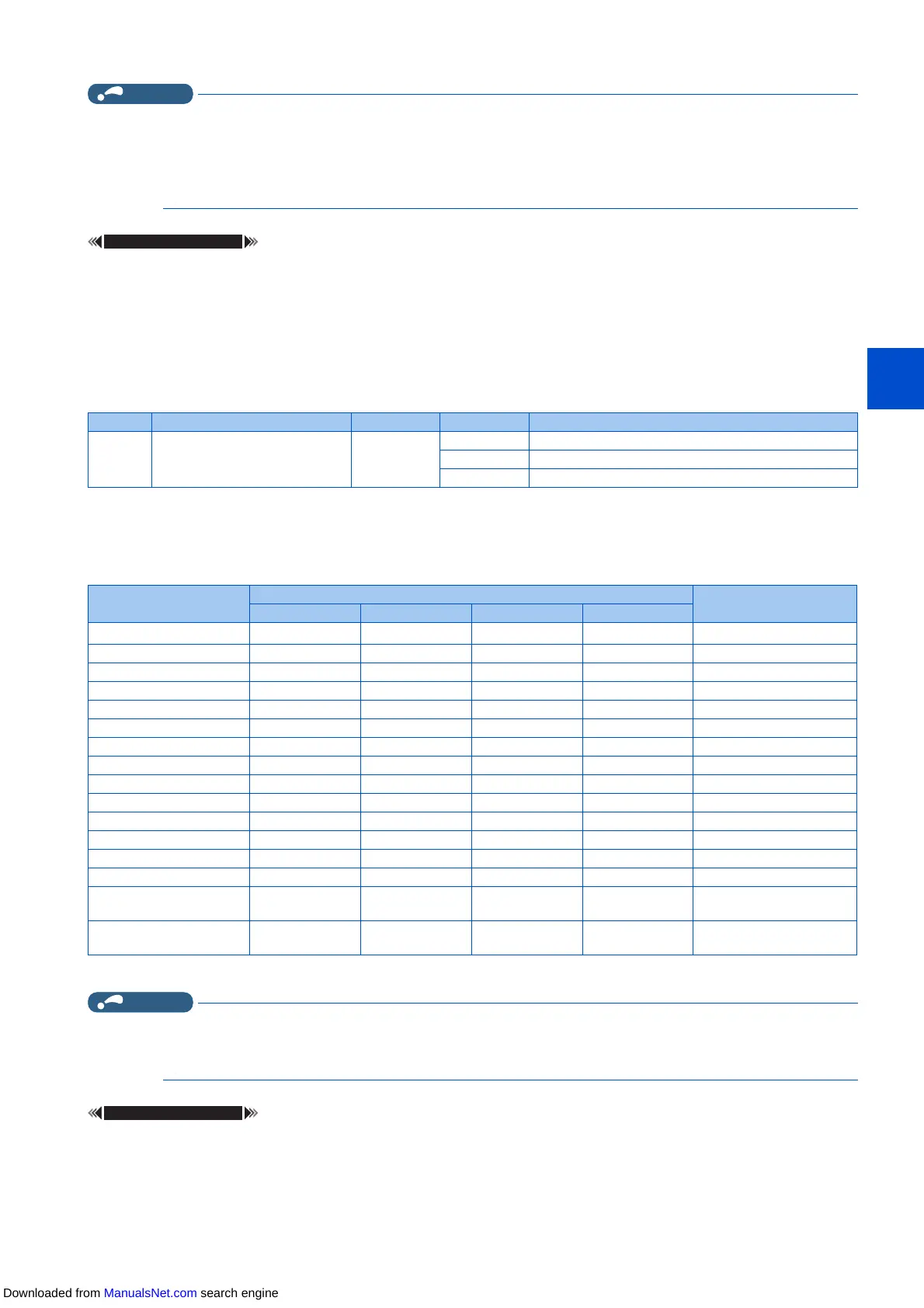
Pr. Name Initial value Setting range Description
76
M510
Fault code output selection 0
0 Without fault code output
1 With fault code output
2 Fault code is output only when a fault occurs
Operation panel
indication (FR-DU08)
Output terminal operation
Fault code
SU IPF OL FU
Normal
*1
00000
E.OC1 00011
E.OC2 00102
E.OC3 00113
E.OV1 to E.OV301004
E.THM 01015
E.THT 01106
E.IPF 01117
E.UVT 10008
E.FIN 10019
E.BE 1010A
E. GF 1011B
E.OHT 1100C
E.OLT 1101D
E.OPT
E.OP1
1110E
Terminals other than the
above
1111F
Downloaded from ManualsNet.com search engine

 Loading...