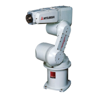
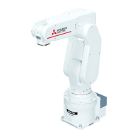
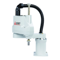
3-55 Outside dimensions/Installation dimensions
3 Controller
Fig.3-14 : Installation of controller (CR3D-700M series)
(
Anchor bolt installation: 4 places)
(
View from upside
)
450
Controller
(upside)
Maintenance area
1
1
0
Front
Approx.
500
Back
500
440
450
300
Side
Approx.
200
Note
1
)
Approx.
Approx.
Side
Note1) The controller sucks in the outside air and discharges the inside air after cooling (Fig. 3-16). The
space required for cooling is 100 mm minimum. Reserve approximately 500 mm of space behind the
unit as the maintenance work area.
Note) As for CE specification, the transformer box is installed in the controller bottom.
Refet to Fig. 3-10
<CR3D-700M series>

 Loading...


